I. 서론
II. 증례
1. Case 1 (DIONAVI, DIO Implant)
2. Case 2 (R2GATETM, Megagen)
III. 총괄 및 고찰
1. Movement of patient
2. Scanning oral structure or model
3. Data merging process
4. Fabrication of guide
5. Positioning surgical guide
6. Gap between metal sleeve and drill
IV. 결론
I. 서론
오늘날 시술의 편리성과 예지성을 동반하는 치료 방법들이 많이 소개되는 가운데, computer-guided flapless implant surgery (guided surgery)가 매우 각광받고 있다. 모든 증례에 이 방법을 적용하기 어렵지만, 적절한 증례에 시술한다면 그 결과는 놀라울 정도로 우수하다11-15. 하지만 정확한 진단이 무엇보다 중요하기에, 막연한 환상과 무리한 시술 계획을 가지고 있다면, 양날의 검처럼 의도하지 않은 의료 과실을 초래할 수도 있다. 본 증례에서는 guided surgery를 이용하여 부분 무치악인 하악 좌측 구치부에 임플란트 식립과 보철을 공통적으로 시술하였는데, 과정과 동반하여 고려해야 할 배경 지식들을 알아보고자 한다. 단순히 과장 광고 혹은 회사 매뉴얼을 비판없이 수용하기보다는 과정
속의 수많은 오차의 누적과 허용 가능한 범위를 가려내어 최대한 계획한만큼의 시술 결과를 얻을 수 있는지가 이 논문의 가치가 있다고 본다.
II. 증례
1. Case 1 (DIONAVI, DIO Implant)
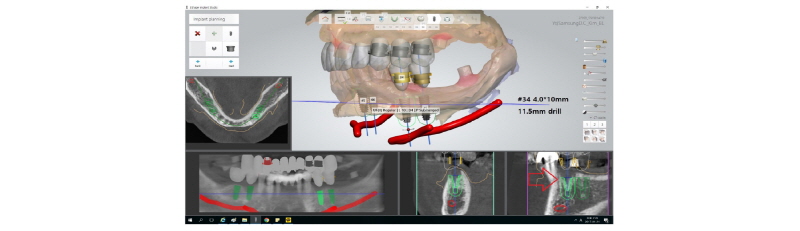
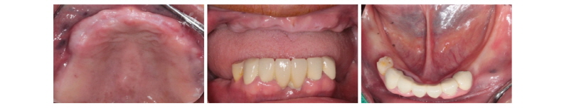
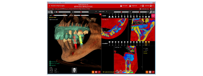
본 60세 여환은 윗니와 양쪽 아래 어금니들이 흔들리고 씹을 때 아프다는 주소로 본원에 내원하여 임상 및 방사선학적 검진 결과 아래와 같이 관찰되었다. #11, 15, 25, 26, 45, 47 치아는 Mob (++/+++) Per (+)와 bone loss, #12, 13, 23은 Per (+)와 root crack line이 관찰되었다. #16, 17, 27, 35, 36, 37 치아는 missing 상태였다. 이에 #11, 12, 13, 15, 23, 25, 26, 45, 47 치아는 hopeless teeth, #16, 17, 27, 35, 36, 37 치아는 missing teeth로 진단되었다(Fig. 1). #11, 12, 13, 15, 23, 24, 26, 45, 47 치아는 발치 후, short dental arch 개념으로 #i13, i14, i15, i23, i24, i25, i34, i35, i45, i46에 implant 식립 및 #i15 부위에 sinus lifting을 계획하였다. 발치 후, 상악은 완전 무치악, 하악은 양측 구치부 무치악이 되었고, 상, 하 rubber impression 채득 후, stone model 제작하였다. CBCT를 촬영 후 bone volume의 양을 계측하여 flapless implant surgery 및 immediate loading을 하기로 하였다. #45, 47 치아의 발치를 시작으로, #12 13 x 15 bridge와 #11 x x 23 x 25 26 bridge 제거 후, #11, 12, 13, 15, 23, 24, 26 치아를 발치하였다. 약 2개월간의 치유기간을 두고, CBCT 재촬영 및 bite 채득으로 vertical dimension 결정하였으며(Fig. 2, 3), 동시에 guided surgery를 준비하였다. 이때, guided surgery를 planning하기 위해서는 CBCT 영상(PHT-30LFO, VATECH)과 alveolar ridge와 soft tissue model을 scanning한 영상(TRIOS® 3, 3Shape, Fig. 4)이 하나로 합쳐진 가상의 영상을 이용하였다. #i13, i14, i23, i24, i25, i34, i35, i45, i46 위치에 implant fixture 식립과 customized abutment와 provisional bridge를 design하였다(Implant Studio®, 3Shape, Fig. 5). 이에 맞춰 3D printer (Projet® 3510HD, 3DSystems)로 surgical guide를(Fig. 6), milling machine (Arum 5X-200, DOOWON)으로 customized abutment와 provisional bridge를 제작하였다(Fig. 10). 임플란트 수술은 2회에 나눠서 시행하였다. 첫 번째 수술일에는 #i13, i14, i15, i23, i24, i25 fixture 식립과(Fig. 7-9) #i15에 lateral approach하여 sinus lifting과 bone graft (Bio-Oss Pen®, Geistlich)를 시행하였다(Fig. 11). 이와 더불어, #i15을 제외한 상악 implant fixture에 abutment 체결 후 provisional bridge를 교합조정하여 합착하였다. 1주일 후, 두 번째 수술일에는 #i34, i35, i45, i46 fixture 식립과(Fig. 9) 동시에 abutment 체결과 provisional bridge를 수복하였다(Fig. 12-16). 마지막 수술을 기점으로 4개월 후에 #i34, i35, i45, i46에 최종 인상 채득하여 도재금관 수복을 하였다(Fig. 17, 18). 향후 상악 임플란트에 대해 보철 예정이다.

|
Fig. 1. Panoramic view before treatment. |
Ju Whan Lee : Computer-guided Flapless Implant Surgery and Immediate Loading with Customized Restoration, Comparing and Reviewing Error of Guided Surgery. Implantology 2017 |

|
Fig. 2. Trial denture base (radiopaque material inserted). Arrows referring the radiopaque markers. |
Ju Whan Lee : Computer-guided Flapless Implant Surgery and Immediate Loading with Customized Restoration, Comparing and Reviewing Error of Guided Surgery. Implantology 2017 |

|
Fig. 3. Bite registration by trial denture base (radiopaque material inserted). |
Ju Whan Lee : Computer-guided Flapless Implant Surgery and Immediate Loading with Customized Restoration, Comparing and Reviewing Error of Guided Surgery. Implantology 2017 |

|
Fig. 4. Intraoral or model scanner, TRIOS® 3, 3Shape used in DIONAVI, DIO Implant. |
Ju Whan Lee : Computer-guided Flapless Implant Surgery and Immediate Loading with Customized Restoration, Comparing and Reviewing Error of Guided Surgery. Implantology 2017 |
|
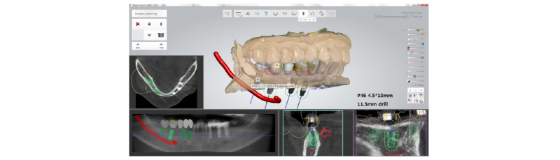
Fig. 5. 3D planning for implant position, customized abutment and provisional bridge (Implant Studio®, 3Shape). |
Ju Whan Lee : Computer-guided Flapless Implant Surgery and Immediate Loading with Customized Restoration, Comparing and Reviewing Error of Guided Surgery. Implantology 2017 |

|
Fig. 6. Surgical guide for maxilla and mandible (DIONAVI, DIO implant). |
Ju Whan Lee : Computer-guided Flapless Implant Surgery and Immediate Loading with Customized Restoration, Comparing and Reviewing Error of Guided Surgery. Implantology 2017 |
|
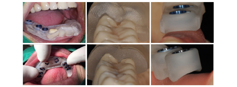
Fig. 7. Intraoral photo taken before guided surgery. |
Ju Whan Lee : Computer-guided Flapless Implant Surgery and Immediate Loading with Customized Restoration, Comparing and Reviewing Error of Guided Surgery. Implantology 2017 |

|
Fig. 8. Surgical guide positioned on maxilla and mandible. |
Ju Whan Lee : Computer-guided Flapless Implant Surgery and Immediate Loading with Customized Restoration, Comparing and Reviewing Error of Guided Surgery. Implantology 2017 |

|
Fig. 9. After surgical drilling sequence, fixture was installed on each site. |
Ju Whan Lee : Computer-guided Flapless Implant Surgery and Immediate Loading with Customized Restoration, Comparing and Reviewing Error of Guided Surgery. Implantology 2017 |

|
Fig. 10. Customized Titanium abutments, provisional bridge and positioning resin jig for maxilla and mandible. |
Ju Whan Lee : Computer-guided Flapless Implant Surgery and Immediate Loading with Customized Restoration, Comparing and Reviewing Error of Guided Surgery. Implantology 2017 |

|
Fig. 11. Sinus lifting via lateral approach was performed on #i15 area with bone graft (Bio-Oss Pen®, Geistlich). |
Ju Whan Lee : Computer-guided Flapless Implant Surgery and Immediate Loading with Customized Restoration, Comparing and Reviewing Error of Guided Surgery. Implantology 2017 |

|
Fig. 12. Frontal intraoral view of provisional bridge cemented on maxilla. |
Ju Whan Lee : Computer-guided Flapless Implant Surgery and Immediate Loading with Customized Restoration, Comparing and Reviewing Error of Guided Surgery. Implantology 2017 |

|
Fig. 13. Customized Titanium abutments were connected on mandible via positioning resin jig. |
Ju Whan Lee : Computer-guided Flapless Implant Surgery and Immediate Loading with Customized Restoration, Comparing and Reviewing Error of Guided Surgery. Implantology 2017 |

|
Fig. 14. Side view of customized Titanium abutments on mandible. |
Ju Whan Lee : Computer-guided Flapless Implant Surgery and Immediate Loading with Customized Restoration, Comparing and Reviewing Error of Guided Surgery. Implantology 2017 |

|
Fig. 15. Side view of provisional bridge on mandible. |
Ju Whan Lee : Computer-guided Flapless Implant Surgery and Immediate Loading with Customized Restoration, Comparing and Reviewing Error of Guided Surgery. Implantology 2017 |

|
Fig. 16. Occlusal view of provisional bridge on mandible. |
Ju Whan Lee : Computer-guided Flapless Implant Surgery and Immediate Loading with Customized Restoration, Comparing and Reviewing Error of Guided Surgery. Implantology 2017 |

|
Fig. 17. PFM bridge (final prosthesis) was cemented on #i35, i36. |
Ju Whan Lee : Computer-guided Flapless Implant Surgery and Immediate Loading with Customized Restoration, Comparing and Reviewing Error of Guided Surgery. Implantology 2017 |

|
Fig. 18. Periapical radiograph on #i35, i36 after final prosthesis. |
Ju Whan Lee : Computer-guided Flapless Implant Surgery and Immediate Loading with Customized Restoration, Comparing and Reviewing Error of Guided Surgery. Implantology 2017 |
2. Case 2 (R2GATETM, Megagen)
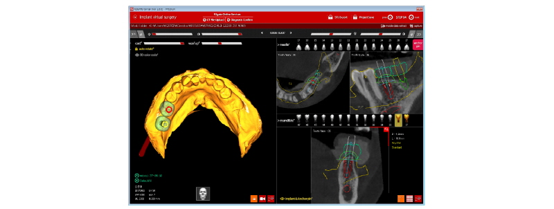
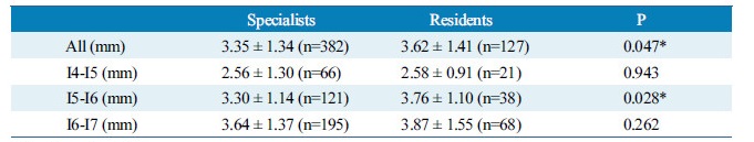
본 59세 여환은 양쪽 위, 아래 큰 어금니가 흔들리고 잇몸이 부었으며 왼쪽 아래 큰 어금니는 오랫동안 없었다는 주소로 본원에 내원하여 임상 및 방사선학적 검진 결과 아래와 같이 관찰되었다. #33 치아는 Mob (+++) Per (+)와 bone loss, #16, 26, 46 치아는 Mob (++/+++) Per (+)와 bone loss, #36, 37 치아는 missing 상태였다. 이에 #16, 26, 33, 46 치아는 hopeless teeth, #17, 36, 37, 47 치아는 missing teeth로 진단되었다(Fig. 19). #16, 26, 33, 46 치아는 발치 후, #i16, i17, i26, i33, i36, i37, i46, i47에 implant 식립과 #i16, i17, i26에 sinus lifting 및 #i33, i46, i47에 GBR을 계획하였다. #i36, i37은 flapless implant surgery 및 immediate loading을 계획하였다. #16, 26, 33, 46 치아를 발치하였고, 2개월 후에, 상, 하 rubber impression 채득 후, stone model 제작하였다. 또한 arch 전용 tray를 bite한 상태로(Fig. 20, 21) CBCT 촬영을 하였다(PHT-30LFO, VATECH). 이후 CBCT 영상과 alveolar ridge와 soft tissue model을 scanning한 영상(TRANSFORMER, Megagen)을 정합하였다. 새로운 영상을 바탕으로 #i36, i37 위치에 implant fixture 식립과 customized abutment와 provisional bridge를 design하였다(R2GATETM, Megagen, Fig. 22, 23). Design대로 3D printer (Perfactory Digital Dental Printer 3, EnvisionTEC) 통해 surgical guide를 제작하였고(Fig. 24) milling machine (TicamPro and WhitecamPro, Megagen)으로 customized abutment와 provisional bridge를 milling하였다(Fig. 28). 임플란트 수술은 5회에 걸쳐서 진행하기로 하였다. 첫 번째 수술일에는 #i36, i37 fixture 식립과 동시에 abutment 체결과 provisional bridge를 합착하였다(Fig. 25-27, 29). 이후, 1개월 후에 #i16, i17 fixture 식립과 lateral approach로써 sinus lifting을 시술하였다. 3개월 후에 #i36, i37에 최종 인상 채득하여 도재금관 수복을 하였다(Fig. 30, 31). 향후 남은 부위에 임플란트 수술 및 보철 진행 예정이다.

|
Fig. 19. Panoramic view before treatment. |
Ju Whan Lee : Computer-guided Flapless Implant Surgery and Immediate Loading with Customized Restoration, Comparing and Reviewing Error of Guided Surgery. Implantology 2017 |

|
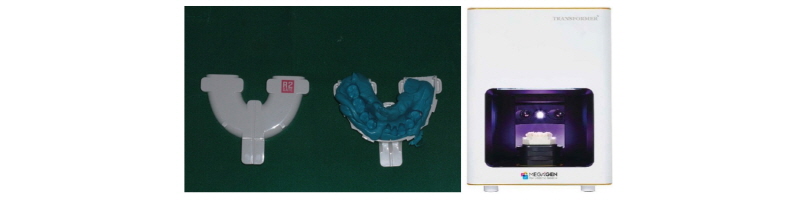
Fig. 20. R2GATETM tray for customized merging, and the tray positioned inside patient’s mouth with bite material. |
Ju Whan Lee : Computer-guided Flapless Implant Surgery and Immediate Loading with Customized Restoration, Comparing and Reviewing Error of Guided Surgery. Implantology 2017 |
|
Fig. 21. (Left) R2GATETM tray upside and downside. (Right) Model scanner, TRANSFORMER, Megagen. |
Ju Whan Lee : Computer-guided Flapless Implant Surgery and Immediate Loading with Customized Restoration, Comparing and Reviewing Error of Guided Surgery. Implantology 2017 |
|
Fig. 22. 3D planning for implant position, customized abutment, provisional bridge (R2GATETM, Megagen). |
Ju Whan Lee : Computer-guided Flapless Implant Surgery and Immediate Loading with Customized Restoration, Comparing and Reviewing Error of Guided Surgery. Implantology 2017 |
|
Fig. 23. 3D planning for implant position especially, analyzing bone density near the position (R2GATETM, Megagen). |
Ju Whan Lee : Computer-guided Flapless Implant Surgery and Immediate Loading with Customized Restoration, Comparing and Reviewing Error of Guided Surgery. Implantology 2017 |

|
Fig. 24. Surgical guide for mandible (upside and downside, respectively). |
Ju Whan Lee : Computer-guided Flapless Implant Surgery and Immediate Loading with Customized Restoration, Comparing and Reviewing Error of Guided Surgery. Implantology 2017 |

|
Fig. 25. Intraoral photo taken before surgery. |
Ju Whan Lee : Computer-guided Flapless Implant Surgery and Immediate Loading with Customized Restoration, Comparing and Reviewing Error of Guided Surgery. Implantology 2017 |

|
Fig. 26. Surgical guide positioned on mandible. |
Ju Whan Lee : Computer-guided Flapless Implant Surgery and Immediate Loading with Customized Restoration, Comparing and Reviewing Error of Guided Surgery. Implantology 2017 |

|
Fig. 27. After surgical drilling sequence, fixture was installed on each site. |
Ju Whan Lee : Computer-guided Flapless Implant Surgery and Immediate Loading with Customized Restoration, Comparing and Reviewing Error of Guided Surgery. Implantology 2017 |

|
Fig. 28. Customized Titanium abutments and provisional bridge for #i36, i37. |
Ju Whan Lee : Computer-guided Flapless Implant Surgery and Immediate Loading with Customized Restoration, Comparing and Reviewing Error of Guided Surgery. Implantology 2017 |

|
Fig. 29. Customized Titanium abutments were connected on #i36, i37. |
Ju Whan Lee : Computer-guided Flapless Implant Surgery and Immediate Loading with Customized Restoration, Comparing and Reviewing Error of Guided Surgery. Implantology 2017 |

|
Fig. 30. PFM bridge (final prosthesis) was cemented on #i36, i37. |
Ju Whan Lee : Computer-guided Flapless Implant Surgery and Immediate Loading with Customized Restoration, Comparing and Reviewing Error of Guided Surgery. Implantology 2017 |

|
Fig. 31. Periapical radiograph on #i36, i37 after final prosthesis. |
Ju Whan Lee : Computer-guided Flapless Implant Surgery and Immediate Loading with Customized Restoration, Comparing and Reviewing Error of Guided Surgery. Implantology 2017 |
III. 총괄 및 고찰
두 명의 환자 증례에서 컴퓨터를 이용한 flapless guided surgery를 시술하였고, 보철은 customized abutment와 provisional bridge를 통해 immediate loading을 하였다. 이후에 최종 수복물로 도재금관 수복하였다. 성별이 같고 연령도 비슷하였으며, 특이할 만한 전신질환은 없었다. 공통적인 시술 부위는 모두 하악 좌측 구치부였고 임플란트 수술 당시에 나타난 골질은 모두 D2였다. 각 증례에 사용한 임플란트 회사는 상이했지만, 모두 Grade IV의 SLA surface를 가진 tapered 형태의 implant fixture (Case 1: UF-II, DIO Implant, Case 2: Anyone®, Megagen)를 식립하였다. Case 1은 직경 4.0 mm, 길이 10 mm이고 internal connection type의 fixture를 2개, Case 2도 마찬가지로 internal connection type의 fixture이었는데, 직경 4.5 mm, 길이 8.5 mm 1개와 직경 4.5 mm, 길이 10 mm 1개 식립하였다. 식립 토크는 모두 35 Ncm 이상이었고, ISQ 값은 80 이상으로 측정되었다. 부위, 골질, 초기고정 등을 바탕으로 2013 ITI consensus 기준의 immediate loading하기 위한 조건에 부합하다고 판단하였다6 (Table 1, 2). 이에 Grade IV titanium block을 milling하여 제작한 customized abutment를 체결한 후, PMMA block milling한 provisional bridge를 임시 합착하였다. 4개월간의 정밀한 관찰 후, osseointegration이 성공적으로 이루어져 최종 인상 채득하여 도재 금관 수복을 하였다. 최종 인상 채득 전에 abutment screw retightening도 실시하였다. Cementation type 보철물을 제작하여 centric stop은 형성하였으나, eccentric movement에서는 간섭 없게 교합조정하였다. 2주간의 경과 관찰동안 환자의 특별한 불편함이나 합병증이 없어 임시 합착 상태에서 유지하기로 하였다.
Table 1. 2013 ITI consensus for loading protocol6 |
|
○: Predictable △: Applied with caution X: Not recommended. Ju Whan Lee : Computer-guided Flapless Implant Surgery and Immediate Loading with Customized Restoration, Comparing and Reviewing Error
of Guided Surgery. Implantology 2017 |
Table 2. 2006 ITI consensus for immediate loading protocoll7 |
|
Ju Whan Lee : Computer-guided Flapless Implant Surgery and Immediate Loading with Customized Restoration, Comparing and Reviewing Error
of Guided Surgery. Implantology 2017 |
본 증례에서와 같이 성공적으로 guided surgery를 진행하였고 customized restoration을 하였는데, 여기에 수반되는 많은 시간과 노력이 필요하다. 구체적으로 진단, 제작, 시술 등에 이르는 과정에서 반드시 원하는 결과가 나타나지 않을 수 있으며, 여기에 대한 이해를 바탕으로 최종 결과를 최대한 비슷하게 이끌어낼 수 있어야 한다4. 따라서 전체 과정에서 나타나는 오차 및 한계를 짚어보고 제공 회사 간의 차이를 살펴보자.
Guided surgery를 하고자 한다면, 아래와 같이 6가지의 오차들을 내포하고 있다16-23.
1. Movement of patient
Hanzelka 등1에 의하면, 환자는 생징후가 있기 때문에 미동을 할 가능성이 있다고 한다. CBCT가 진단 단계에서 필요한데, CBCT 촬영 도중 이 미동으로 인해 영상의 왜곡이 나타날 수 있으며, 이로 인해 부정확한 영상이 나타날 수밖에 없다. 또한 CBCT 기계의 작동음과 진동에 의해서 환자가 놀란 반응을 일으키면 마찬가지로 의도치 않게 영상이 정확하지 않을 수 있다. 약 1 mm 내외의 움직임이 나타난다고 하였으며, 이것이 중요한 해부학적 구조물이 지나는 부위에 임플란트 시술하고자 한다면, 진단부터 오류 발생이 가능한 것이다(Fig. 32).
|
Fig. 32. Movement appeared on the CBCT image by patient. |
Ju Whan Lee : Computer-guided Flapless Implant Surgery and Immediate Loading with Customized Restoration, Comparing and Reviewing Error of Guided Surgery. Implantology 2017 |
2. Scanning oral structure or model
Hack 등2에 의하면, 다양한 구강 스캐너들 통한 실질적인 모델과의 오차를 연구한 것이다. 3Shape사의 Trios가 가장 오차가 적고 나머지 제조사들은 컸지만, 일반적으로 CT오차보다 수치가 훨씬 적어 큰 문제는 없다. Trueness가 원래 참값과 측정값간의 차이로써 오차의 개념이고, Precision은 측정값들 사이의 편차로 재현성의 개념이다. 따라서 본 증례에서 사용한 3Shape사의 TRIOS® 혹은 Megagen사의 TRANSFORMER 모두 10 µm 내외의 오차와 재현성이 있기에 임상적으로 허용할 만하다고 볼 수 있다(Table 3).
Table 3. Trueness and Precision of the six intraoral scanners2 |
|
Ju Whan Lee : Computer-guided Flapless Implant Surgery and Immediate Loading with Customized Restoration, Comparing and Reviewing Error
of Guided Surgery. Implantology 2017 |
Ahiholm 등3에 의하면, 구강 스캐너를 사용하는 데 있어서, crown and bridge까지는 임상적으로 허용할 만한 오차가 있으나, full arch의 경우 conventional impression technique을 추천한다고 하였다. 앞선 선행 연구에서 구강 스캐너의 뛰어난 해상도와 실물과 근접한 영상 획득이 가능하나, 고질적으로 변곡점이 있는 곡선 부위 혹은 수직적으로 큰 높이차가 있는 구조물의 경우, 정확성은 유의미하게 많이 감소된다고 여러 연구들에서 보고하였다고 한다. 따라서 short span의 경우에 사용 가능할지라도 정확성이 매우 중요한 목표이기에 많은 경우에 있어서 별도로 환자 구강 내 rubber impression을 통해 stone model을 제작하여 intraoral scanner가 아닌 model scanner 통해서 신뢰할 만한 scanning image를 획득하고자 한다.
3. Data merging process
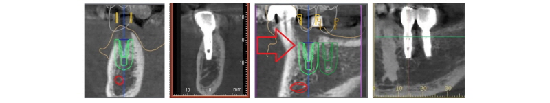
Guided surgery를 하는 데에 있어서 여러 장치들을 사용하고, 이 장치들의 정보를 모아서 가상의 이미지를 만드는데, 여기에 2가지 file이 있다. CBCT 촬영으로 얻은 DICOM file (Digital Imaging and COmmunications in Medicine file)과 intraoral or model scanning해서 얻은 STL file (STereoLitho-graphy file)이다. 이후 DICOM file과 STL file이 서로 정합되는 과정이 필수인데, 차이가 항상 있기 마련이다. 즉, STL image 상에서 DICOM image를 overlap시키면 outline에 차이가 생기고, 반대로 DICOM image 상에서 STL image를 overlap시키면 마찬가지로 차이가 생긴다. 여기서 어떤 software는 둘의 차이를 사용자가 조절 가능하지만, 어떤 software는 자체 내 logic에 의해 강제적으로 벡터와 길이의 평균값으로 정합한다. 이에 실질적인 구강 내 구조와 차이가 필히 발생할 수밖에 없어, 자칫 원하지 않은 위치로 implant를 위치시킬 가능성을 배제할 수 없다.
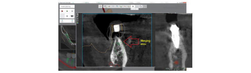
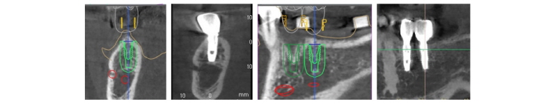
Fig. 33, 34를 보면, 이 2가지를 정합해보니, 오차가 발생하였다. 이 증례의 경우에 사용한 software는 3Shape사의 Implant Studio®이었다. #i43, i44, i46, i47 부위에 식립하는 것이었는데, #i46번 자리에 정합오차가 발생했다. Buccolingual로 soft tissue의 외형이 분홍색 선이고, buccal은 연조직 두께가 보이지만, lingual은 보이지 않고 bone outline과 일치하였다. 즉, lingual 측에서 정합 오차가 발생한 것이다. Radiopaque marker에 의해서 강제 처리되어 path, depth, position을 정했고 식립 후에 촬영한 CT 단면과 overlap시킨 결과, 계획하던 위치에서 벗어난 것을 볼 수 있다. 여기서는 lingual side에 cortical layer가 두꺼워서 수술 당시 최대한 lingual로 밀착시켰어도 buccal로 drill과 fixture가 밀린 것을 알 수 있다.
|
Fig. 33. 3D planning case for #i43, i44, i46, i47 area via Implant Studio®, 3Shape. |
Ju Whan Lee : Computer-guided Flapless Implant Surgery and Immediate Loading with Customized Restoration, Comparing and Reviewing Error of Guided Surgery. Implantology 2017 |
|
Fig. 34. Merging error occurred during analyzing the #i46 area of the above case. The pink outline surrounding the bone represents the gingiva or mucosal line. However, the line overlaps with the lingual bony outline, which means the merged image is not proper. Also, the radiographic size of radiopaque marker does not fill in the outline of the actual size of the marker, either. |
Ju Whan Lee : Computer-guided Flapless Implant Surgery and Immediate Loading with Customized Restoration, Comparing and Reviewing Error of Guided Surgery. Implantology 2017 |
본 증례에서 Case1에서도 3Shape사의 Implant Studio® software를 사용하였고 다행히 정합 오차는 발생되지 않았다(Fig. 35).

|
Fig. 35. 3D planning of case 1 aforementioned. #i34, i35 are analyzed and no merging error has occurred. |
Ju Whan Lee : Computer-guided Flapless Implant Surgery and Immediate Loading with Customized Restoration, Comparing and Reviewing Error of Guided Surgery. Implantology 2017 |
이러한 정합오차를 최소화하기 위해 Megagen사의 R2GATETM의 merging process는 차이가 있다. 앞선 증례에서 radiopaque marker를 이용한 것과 달리, radiopaque한 arch 모양의 R2GATETM tray를 이용하였다. 이 tray를 환자가 문채로 CBCT 촬영하고 얻은 DICOM file과 model scanning해서 얻은 STL file을 정합하면, customized merging을 하게 된다. 따라서 강제 정합이 아니기에 상대적으로 더 정확한 이미지 획득이 가능하다(길이 or 체적의 최적화 문제). 골질 분석에서도 차이가 있다. 대부분의 CBCT 기계에서 제공하는 CT image는 256단계의 흑백 스케일로써, 색의 명도 스펙트럼처럼 흰색과 검정색의 다양한 조합으로 표현된다. 그리고 CBCT 제조사들마다 특정 영역의 흑백 스케일에 치중되어있는데, CT image가 더 밝게 보일 수도, 더 어둡게 보일 수도 있다8-10. Megagen의 R2GATETM에서는 이 256단계의 흑백스케일을 색으로 재정렬을 하였다. 이것을 digital eye라고 하며, 특정 알고리즘에 의해 black, red, blue, yellow, green color로 변환된 것이다. 이에 따라 골질의 상세한 분석이 가능한 것이다. 각 색의 해석은 다음과 같다. Black은 공기, red는 연조직, blue는 해면골, yellow는 치밀골, green은 더 치밀한 치밀골을 표현한다. 각 색 영역에서 %의 의미는 단단한 골량의 비율을 나타낸 값이다(Fig. 36). 이로써 image의 밀도를 직관적으로 분석 가능하여, implant 식립에 있어서 해당 골에 밀도가 낮은 red가 많을수록 초기 고정에도 불리하고 치유기간이 길어질 수밖에 없으며, immediate loading을 시도한다면 위험한 결과를 초래할 수 있다고 예상할 수 있다.

|
Fig. 36. Digital-EYE in R2GATETM, Megagen. The DICOM file of CBCT originally represents 256 scale of black and white. However, precise analysis of bone density is not available through the original CT image. Hence, the digital eye supplies and helps to analyze detailed bone density. It converts the 256 scale of black and white to black/red/blue/yellow/green spectrum by specific algorism. The color refers to the following structure; black-air, red-soft tissue, blue-cancellous bone, yellow-cortical bone, green-denser cortical bone. The percentage above the color means the quantitative bone density. The higher the percentage, the denser the bone. |
Ju Whan Lee : Computer-guided Flapless Implant Surgery and Immediate Loading with Customized Restoration, Comparing and Reviewing Error of Guided Surgery. Implantology 2017 |
4. Fabrication of guide
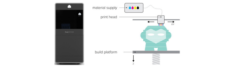
DIONAVI에서 사용하는 3D printer는 3D Systems사의 Projet® 3510HD이다(Fig. 37). 이것은 multijet printing technique을 사용한다고 한다. 이는 흔히 casting crown 제작하기 위해서 wax-up 후 매몰하여 burn-out한 다음 casting하는 방법과 유사하다. Print head가 liquid와 powder를 혼합하여 전후 왕복 운동하면서 platform에 분사하면, 동시에 platform은 수직방향으로 아래로 하강하게 되며, 이로써 layering으로 아래에서부터 위까지 겹겹이 쌓아서 원하는 조형물을 얻는 방식이다(Fig. 37). 3D printer의 해상도는 DPI가 단위라고 한다. 예를 들어, 구를 구현하기 위해서 모니터는 pixel 단위로써 display만하므로 많은 화소가 자세히 필요치는 않다. 반면에 printer는 실제적인 모형을 재현해야 하기 때문에 화소 아닌 DPI로 촘촘히 모여서 구를 만든다. 이렇듯 작은 점들이 X, Y, Z방향으로 흩뿌림으로써 구의 형상을 갖추는 것이다(Fig. 38). 해당 기계의 해상도는 고해상도이고 정확도의 오차는 50 µm로써 만족할 만한 수준의 결과물이 나온다.
|
Fig. 37. (Left) 3D printer. Projet® 3510HD, 3D Systems utilized in DIONAVI, DIO implant. (Right) Principle of multijet printing (courtesy of rookie electronics.com., used by permission). |
Ju Whan Lee : Computer-guided Flapless Implant Surgery and Immediate Loading with Customized Restoration, Comparing and Reviewing Error of Guided Surgery. Implantology 2017 |

|
Fig. 38. Explaining how a monitor or printer represents a sphere. Since a monitor displays rough image, it does not need high resolution (lower value of pixels is acceptable). However, a printer needs a higher value of DPI (dots per inch) in order to represent a similar sphere on a paper, for example. |
Ju Whan Lee : Computer-guided Flapless Implant Surgery and Immediate Loading with Customized Restoration, Comparing and Reviewing Error of Guided Surgery. Implantology 2017 |
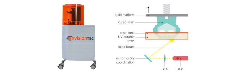
Megagen에서 사용하는 3D printer는 EnvisionTEC사의 Perfactory Digital Dental Printer 3이고, digital light processing technique을 이용한다. 프로젝터를 광원으로 하여 특정 파장의 빛이 거울에 반사되어 liquid와 powder가 혼합된 액상수지에 투영되면, 동시에 platform은 수직 방향으로 상승하면서 우리가 원하는 조형물이 이 빛에 의해 경화되는 것이다(Fig. 39). 해당 기계의 해상도는 고해상도이고 정확도의 오차는 25 µm로써 더 만족할 만한 수준의 결과물이 나온다.
|
Fig. 39. (Left) Perfactory Digital Dental Printer 3, EnvisionTEC (Right) Principle of digital light processing technique (courtesy of rookie electronics.com., used by permission). |
Ju Whan Lee : Computer-guided Flapless Implant Surgery and Immediate Loading with Customized Restoration, Comparing and Reviewing Error of Guided Surgery. Implantology 2017 |
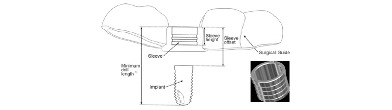
3D printer의 성능이 매우 우수하기 때문에 그 정확도는 앞서 언급하였다시피 마이크로 단위의 오차로 제작되어질 수 있고 심지어 스캐너도 실물과의 오차도 극히 작기 때문에 임상적으로는 허용 가능한 범위내에 있다고 하였다. 따라서 scanning, 정합, printer의한 제작까지의 과정은 넘어가고 여기서는 전체 guide 제작 과정 중, metal sleeve를 삽입하는 것에 초점을 맞추겠다. 삽입 과정은 기계가 아닌 수작업으로 직접하는 것이다. 순접같은 접착제로 붙이는 게 아니라 metal sleeve를 guide 내 printer에 의해 형성된 hole에 접합시키고 회전해서 형태적인 retention의해 고정된다고 한다. 뒤에서도 언급하겠지만 drill과 metal sleeve사이는 꽉 끼는 밀착 구조가 아니라 gap이 존재한다(Fig. 40). Drill의 대략적인 path만 잡아줄 뿐이지 실제로 drill 넣으면 헐겁다. Path가 완벽할 것이라는 맹신은 하지 않는 게 좋다. Drill을 hole에 삽입 시, 정확히 수직이 아니더라도 tilting된 각도에도 drill이 metal sleeve를 통과할 수도 있기 때문이다. 그로 인한 일련의 drilling이 잘못되어 원하지 않는 위치에 임플란트를 식립하면 error가 발생한다.
|
Fig. 40. Sectioned diagram of the metal sleeve within the surgical guide. |
Ju Whan Lee : Computer-guided Flapless Implant Surgery and Immediate Loading with Customized Restoration, Comparing and Reviewing Error of Guided Surgery. Implantology 2017 |
하지만, Megagen R2GATETM에서는 오로지 resin based surgical guide만 제작하고 metal sleeve는 사용하지 않는다. 별도의 metal sleeve 없이 자체적인 drill stopping 기능을 부여하였으며, drilling 시에 tilting됨 없이 path 유지가 가능하다.
5. Positioning surgical guide
Distal free end 혹은 full edentulous case 경우 guide positioning이 일정하지 않다. Guide가 정확히 구강내에 안착이 되지 못하고 뜨는 경우가 발생 가능하다(Fig. 41). 이 error 요소가 가장 많은 변위가 발생 가능한 경우이다. 이렇게 잘못 위치시킴으로써 벌어지는 후속 결과는, 잘못된 drilling 축적으로 이어져 fixture path 혹은 depth가 계획하던 것에 벗어나게 되는 것이다.
|
Fig. 41. Error can occur if surgical guide is not positioned appropriately. |
Ju Whan Lee : Computer-guided Flapless Implant Surgery and Immediate Loading with Customized Restoration, Comparing and Reviewing Error of Guided Surgery. Implantology 2017 |
6. Gap between metal sleeve and drill
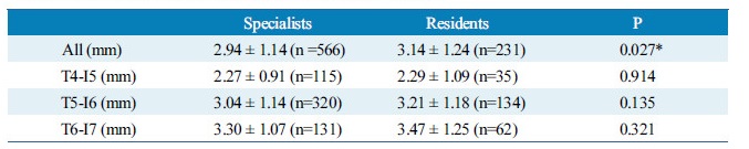
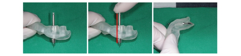
앞서 설명한 것처럼, 통상 metal sleeve와 drill 사이의 gap, 공차 혹은 유격이 존재하는데, guide 제작 회사마다 다르다(Fig. 42, 43). Park 등5에 의하면, 각 회사별 공차를 연구했는데, 단순히 숫자의 비교로 각 시스템의 우열을 판가름하기 어렵다고 한다. 즉, 수술 시 부드러운 drilling에 따른 편의성의 측면(공차가 상대적으로 큼)과 guide의 정확도의 측면(공차가 상대적으로 작음)에서, 어느 쪽에 치중할지에 대한 견해의 차이일 뿐이라고 한다. 그렇지만 이것은 중요한 사안이라고 봐야 한다. 자세히 내용을 살펴보면, initial drill, 2.0 mm twist drill, fixture mount 등 모든 drill과 metal sleeve 사이의 유격으로 인해서 그 drill이 기울어지는 각도들의 평균값을 보여준 것이다. 2.0 mm drill 사용 시 각도가 틀어짐으로 해서 나타나는 drill tip의 변위가 apex에서 최대 3 mm가 될 수 있으므로 주의를 요한다. 해당 연구에서의 결과에서 보듯, 아주 중요한 사안이 될 수밖에 없다. 즉, path가 기울어짐으로써 잘못된 drilling으로 인해 우리가 계획한 것이 아닌 잘못된 위치에 implant를 식립할 위험이 있다는 것이다. 해당 증례는 헐거운 metal sleeve를 통해 #i47 drilling 과정에서 기존 drill path에서 어긋나기 시작하여 fixture 식립할 때 하악 구치부 치밀골 하방의 해면골로 빠졌다(Fig. 44).

|
Fig. 42. DIONAVI, DIO Implant surgical guide and drill. Notice the inclination of the drill when given a lateral force. |
Ju Whan Lee : Computer-guided Flapless Implant Surgery and Immediate Loading with Customized Restoration, Comparing and Reviewing Error of Guided Surgery. Implantology 2017 |
|
Fig. 43. R2GATETM, Megagen surgical guide and drill. No inclination appeared in tactile nor visual sense. |
Ju Whan Lee : Computer-guided Flapless Implant Surgery and Immediate Loading with Customized Restoration, Comparing and Reviewing Error of Guided Surgery. Implantology 2017 |

|
Fig. 44. (Left) Surgical failure can occur if the path is not well maintained through the drilling sequence. In this case, metal sleeve of surgical guide cannot offer an advantage for flapless implant surgery. Consequently, the mispath lead #i47 implant fixture to go too far away. (Right) Implant fixture on #i47 area was explanted, fortunately leaving no nerve damage. |
Ju Whan Lee : Computer-guided Flapless Implant Surgery and Immediate Loading with Customized Restoration, Comparing and Reviewing Error of Guided Surgery. Implantology 2017 |
따라서 이상 6가지의 오차 요소들을 살펴본 결과, 환자의 움직임을 통제하고 수술 시 surgical guide를 재위치시키는 것만 제대로 해준다는 가정하에서, scanner의 성능은 유사하게 우수하기 때문에, 결국 data merging error와 guide 제작 및 파생적으로 guide 내 metal sleeve의 유무에 따라 상대적으로 더 정확한 guide system이 될 수 있음을 입증할 수 있다.
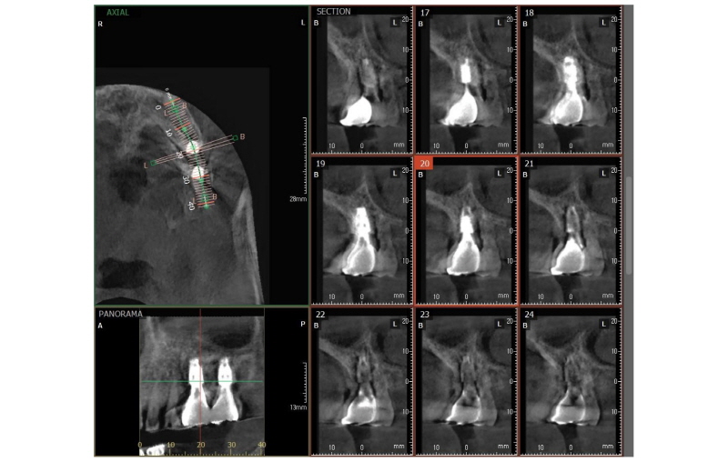
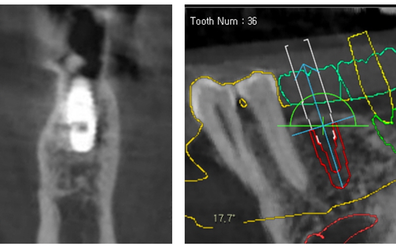
아래는 본 증례에서 식립한 임플란트와 계획한 임플란트의 위치, 방향, 깊이를 비교했다. 모두 만족할 만한 결과를 보였다(Fig. 45-48).
|
Fig. 45. Comparison between planning and installed images via DIONAVI, DIO implant (#i34 area of case 1). |
Ju Whan Lee : Computer-guided Flapless Implant Surgery and Immediate Loading with Customized Restoration, Comparing and Reviewing Error of Guided Surgery. Implantology 2017 |
|
Fig. 46. Comparison between planning and installed images via DIONAVI, DIO implant (#i35 area of case 1). |
Ju Whan Lee : Computer-guided Flapless Implant Surgery and Immediate Loading with Customized Restoration, Comparing and Reviewing Error of Guided Surgery. Implantology 2017 |
|
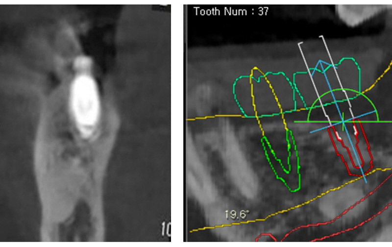
Fig. 47. Comparison between planning and installed images via R2GATETM, Megagen (#i36 area of case 2). |
Ju Whan Lee : Computer-guided Flapless Implant Surgery and Immediate Loading with Customized Restoration, Comparing and Reviewing Error of Guided Surgery. Implantology 2017 |
|
Fig. 48. Comparison between planning and installed images via R2GATETM, Megagen (#i37 area of case 2). |
Ju Whan Lee : Computer-guided Flapless Implant Surgery and Immediate Loading with Customized Restoration, Comparing and Reviewing Error of Guided Surgery. Implantology 2017 |
IV. 결론
Guided surgery에서의 error 과정은 어떻게 보면 가장 중요한 핵심일 수 있다. 왜냐하면 guided surgery는 simulation을 통한 임상 적용이라, 그 차이는 항상 있기 마련이기 때문이다. 즉, 어떠한 tool이건 완벽한 재현은 어렵다는 것이다. 하지만 출발점이 좋아야 종착점이 마찬가지로 좋을 수 있듯이, 진단이라는 출발점에서 정확성을 요한다면, R2GATETM 통한 guided surgery를 강력하게 추천할 수 있다.


