


Ⅰ. Introduction
Implant restoration in the maxillary anterior region is associated with high esthetic and functional demands, and even minor inaccuracies in implant position transfer may lead to misfit of the definitive prosthesis, occlusal discrepancies, and compromised esthetic outcomes.1 Therefore, accurate transfer of implant position during the digital impression process is essential to ensure passive fit of the definitive prosthesis and to reduce the risk of mechanical complications such as screw loosening, component fracture, and prosthetic failure.2
Although the intraoral scanner (IOS) technology has advanced considerably in recent years, inaccuracies in implant position transfer may still occur. In the anterior region, intraoral digital impressions may be particularly susceptible to cumulative stitching errors as the scanning pathway crosses the dental midline, potentially affecting the accuracy of implant position transfer.3,4 This susceptibility may be further influenced by the relatively symmetric morphology and limited anatomical reference structures characteristic of the maxillary anterior region.3,4
IOSs have been increasingly incorporated into integrated digital workflows for implant rehabilitation.5 Accordingly, considerable attention has been directed toward identifying digital impression parameters that influence the accuracy of implant position transfer.3,4,6 One important parameter is the scan body (SB), which serves as the reference structure linking the implant fixture to the digital workflow.7 The scanned SB geometry is then matched with the corresponding library file, allowing the software to estimate the three-dimensional implant position and axial orientation.3 Previous studies have reported that SB-related factors, including surface material, geometry, and structural characteristics, may influence the accuracy of digital implant impressions.4,8 More recently, supragingival SB exposure height has emerged as a potential clinical factor that may affect scan data acquisition and the accuracy of implant position reconstruction.8,9,10
Previous in vitro studies have reported that a reduced supragingival SB exposure height, particularly below approximately 6 mm at anterior implant sites, may adversely affect the accuracy of IOS-based digital implant impressions by increasing linear deviation (LD) and angular deviation (AD).4,8,9 However, clinical in vivo evidence regarding the influence of supragingival SB exposure height on the accuracy of IOS-based implant position transfer at maxillary anterior implant sites remains limited. Clinical scanning conditions, including soft tissue dynamics, patient movement, and limited anatomical reference structures in the anterior region, may differ substantially from those in controlled laboratory environments.8
Therefore, the purpose of this clinical pilot study was to evaluate the influence of supragingival SB exposure height on the accuracy of intraoral digital implant impressions at maxillary anterior implant sites by recording the iterative closest point (ICP) registration root mean square (RMS) error and quantifying site-level LD and AD.
The null hypothesis was that the supragingival SB exposure height would not influence digital impression accuracy.
Ⅱ. Materials and Methods
This study was designed as a retrospective clinical pilot analysis based on pre-existing clinical records and digital datasets from a single patient. No additional clinical procedures were performed for this study. The study was conducted in accordance with the principles of the Declaration of Helsinki, and the protocol was exempted from full review by the Institutional Review Board of Dankook University Dental Hospital (IRB Exemption No. DKUDHIRB 2025-10-004).
A 45-year-old female patient classified as American Society of Anesthesiologists (ASA) physical status I was included. The patient presented with missing maxillary central incisors and two internal-connection implants placed at the maxillary lateral incisor sites (#12 and #22) (Luna, 3.4 × 10 mm; Shinhung Co., Ltd., Seoul, South Korea). This case was selected because complete conventional and digital impression datasets from both provisional and definitive prosthetic phases were available for retrospective analysis. Five months after implant placement, successful osseointegration was achieved, and prosthetic treatment was initiated.
To fabricate the temporary implant-supported fixed dental prosthesis, an open-tray polyvinyl siloxane (PVS) impression was obtained using compatible impression copings, and Type IV dental stone was poured into the impression to produce a single stone cast containing implant laboratory analogs. The seating of the impression copings was verified clinically and confirmed by radiography (Figs. 1A and 1B). During the provisional prosthetic phase, an intraoral digital impression was acquired using a compatible TS mini-Short SB (overall length, 8 mm; Osstem Implant Co., Seoul, South Korea) to generate the Short SB dataset. At a subsequent clinical appointment for fabrication of the definitive implant-supported fixed dental prosthesis, an intraoral digital impression was obtained using a compatible TS mini-Long SB (overall length, 12 mm; Osstem Implant Co.), generating a Long SB dataset.
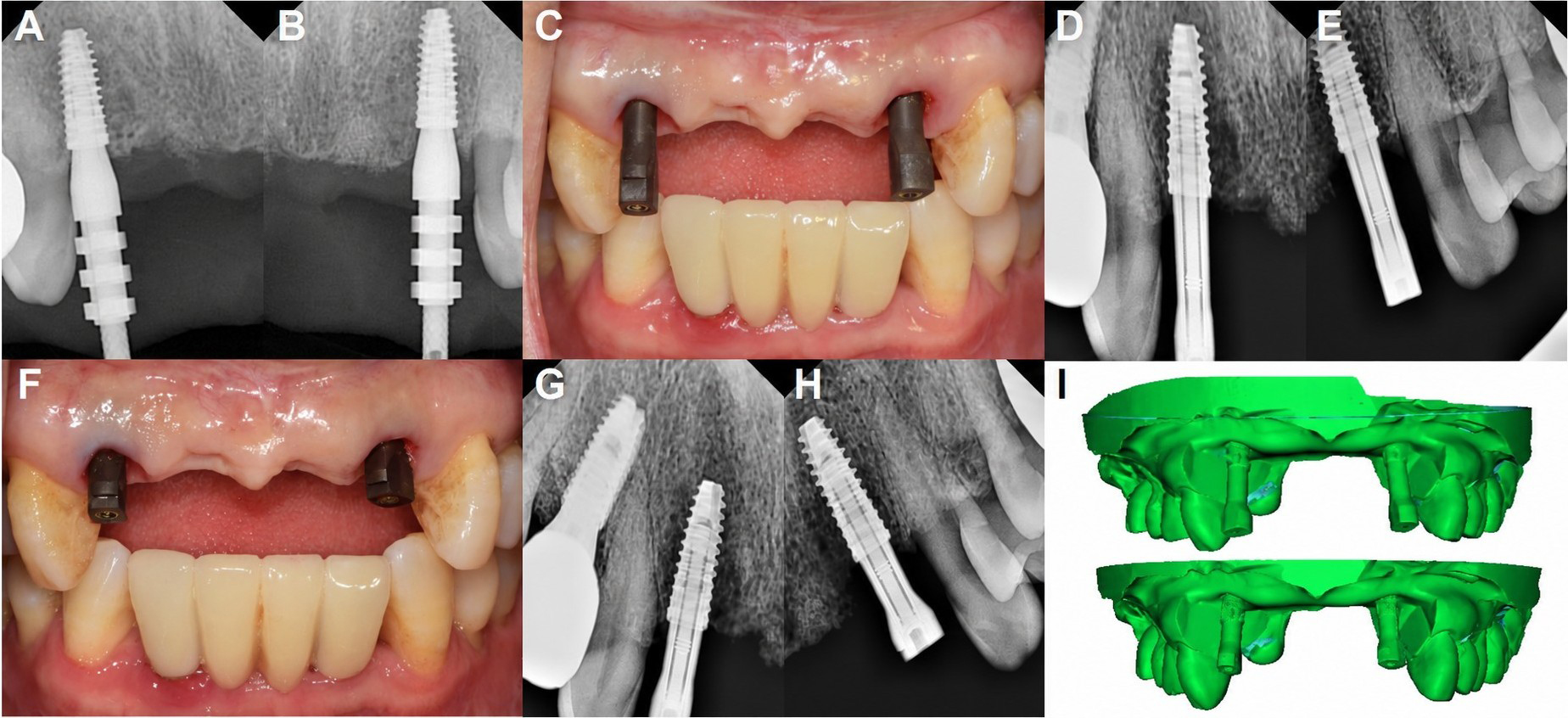
Fig. 1.
Impression component seating and reference model scans. (A, B) Radiographic confirmation of impression coping seating, (C) Intraoral photograph of the Long SB, (D, E) Radiographic confirmation of Long SB seating, (F) Intraoral photograph of the Short SB, (G, H) Radiographic confirmation of Short SB seating, (I) Reference STL datasets generated from the conventional impression-derived stone cast. Top, Long SB; bottom, Short SB. SB, scan body; STL, standard tessellation language.
All intraoral scans were obtained using an IOS (TRIOS 5; 3Shape A/S, Copenhagen, Denmark) by the same operator according to the manufacturer’s recommended scanning protocol. The seating of both the Long and Short SBs was verified clinically and radiographically. Representative intraoral photographs and radiographs of the seated SBs are shown in Figs. 1C to 1H. Each intraoral scan was exported in the standard tessellation language (STL) format as a separate dataset.
For deviation analysis, condition-specific reference datasets were generated from a pre-existing stone cast. Each SB was seated on the same stone cast and digitized using a laboratory scanner (Medit T500; Medit Corp., Seoul, South Korea). The Long and Short SBs were seated and scanned to produce the Long SB and Short SB reference datasets, respectively (Fig. 1I). Both reference datasets were derived from the same conventional impression-derived stone cast but differed only in the seated SB.
Supragingival SB exposure height was measured in the cross-sectional views of each IOS STL dataset as the shortest linear distance from the most coronal point of the peri-implant gingival margin adjacent to the SB to its most coronal surface. Measurements were obtained by a single examiner at sites #12 and #22 using dental computer-aided design (CAD) software (Exocad DentalCAD; Exocad GmbH, Darmstadt, Germany).
All STL datasets (the Short SB and Long SB reference datasets and the corresponding Short SB and Long SB IOS datasets) were imported into open-source 3D point cloud processing software (CloudCompare v2.14 alpha; EDF R&D, Paris, France) for deviation analysis.11,12 Each IOS dataset was aligned to its corresponding (same SB type) reference dataset using ICP registration with a point-to-plane distance metric. The peripheral regions with incomplete or less reliable scan data were excluded using a partial overlap threshold.
For each SB condition, an ICP registration RMS error was obtained from the corresponding IOS-reference dataset pair. This value was derived from the selected overlapping region of the registered dataset, which included both implant sites and served as a dataset-level residual registration metric. It was not calculated separately for the individual implant sites. The ICP registration RMS error was calculated as the RMS of the residual point-to-surface distances between the IOS and reference datasets as follows:
where is the number of measured points, and is the residual point-to-surface distance between each point in the IOS dataset and the corresponding surface of the reference dataset.
To quantify the site-level geometric deviations related to implant position and orientation transfer, LD and AD were calculated using cylinder fitting of the SB geometry. For the cylinder fitting, the SB region was isolated from each STL dataset. The surrounding tooth, soft tissue, and cast surfaces were removed, and only the visible SB surface was retained as an SB mesh. For each dataset and implant site, a virtual cylinder was fitted to the SB mesh in both the IOS dataset and its corresponding reference dataset using the Random Sample Consensus (RANSAC) algorithm.13 The centroid and axial vectors obtained from each fitted cylinder were extracted and used for deviation analysis. LD was calculated as the Euclidean distance between the centroids of the reference and IOS cylinders:
where (, , ) and (, , ) denote the centroid coordinates of the reference and IOS cylinders, respectively.
AD was defined as the angle between the axial vectors of the reference and IOS cylinders:
where and represent the axial vectors of the reference and IOS cylinders, respectively.
Because this was a retrospective, single-patient pilot study, inferential statistical analyses were not performed. The supragingival SB exposure height, ICP registration RMS error, LD, and AD were reported descriptively.
Ⅲ. Results
The supragingival SB exposure-height measurements are summarized in Table 1. Mean supragingival SB exposure heights were 6.39 mm and 2.73 mm for the Long SB and Short SB conditions, respectively. The representative cross-sectional images used for these measurements are shown in Fig. 2. The ICP registration RMS error, calculated for the entire registered dataset including both implant sites, was 29.8 µm in the Long SB condition and 70.4 µm in the Short SB condition (Table 2). The color-coded deviation maps demonstrate deviations closer to zero in the Long SB dataset, whereas the Short SB dataset exhibits more extensive positive and localized negative surface deviations (Fig. 3).
Table 1.
Supragingival scan body exposure height and deviation outcomes by scan body condition and implant site
| Long scan body | Short scan body | |||||
| #12 | #22 | Mean | #12 | #22 | Mean | |
| Exposure height (mm) | 6.76 | 6.01 | 6.39 | 3.01 | 2.44 | 2.73 |
| LD (mm) | 0.98 | 1.36 | 1.17 | 1.17 | 1.52 | 1.35 |
| AD (°) | 1.35 | 0.34 | 0.85 | 2.40 | 4.97 | 3.68 |
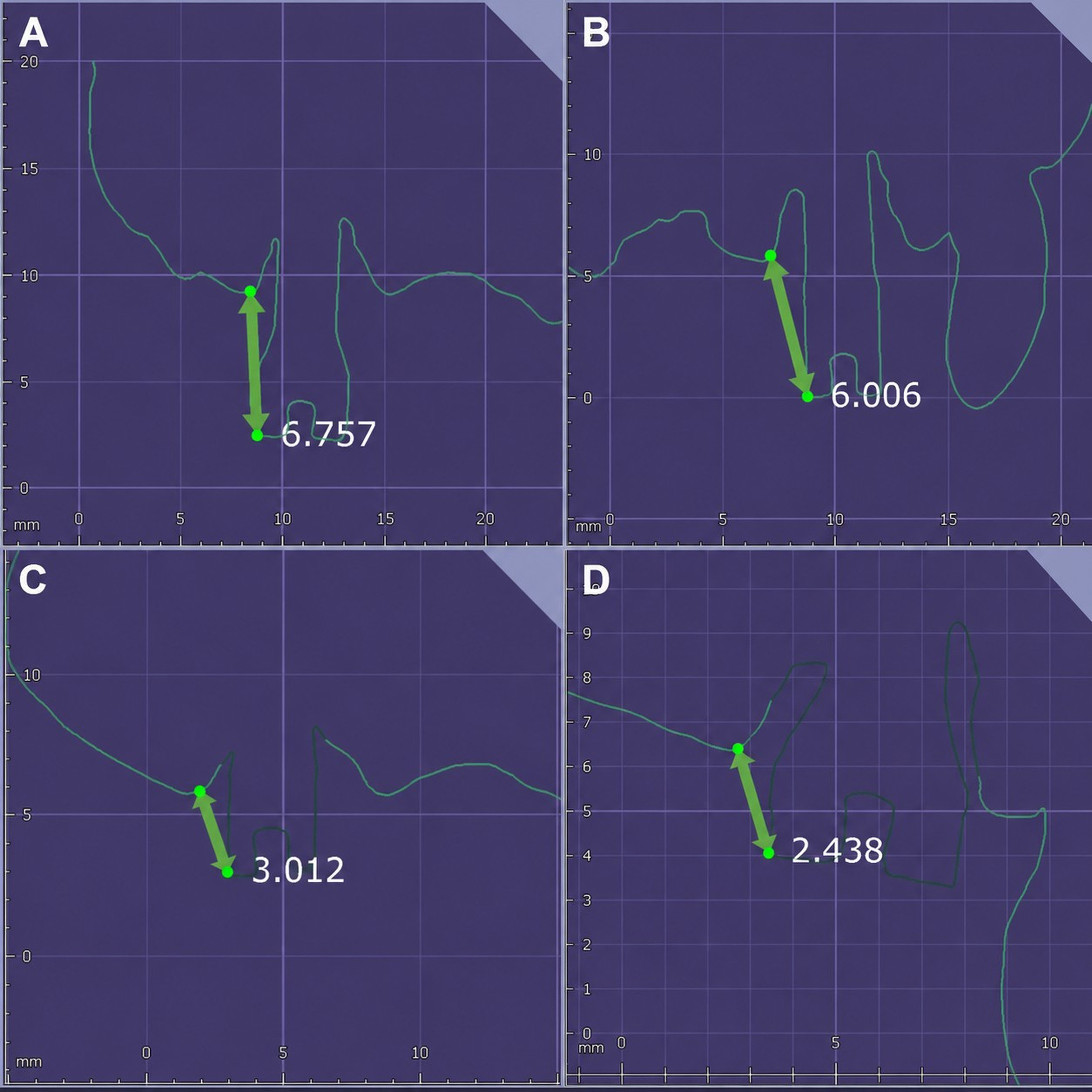
Table 2.
ICP registration RMS error by scan body condition
| Long scan body | Short scan body | |
| ICP registration RMS error (µm) | 29.8 | 70.4 |
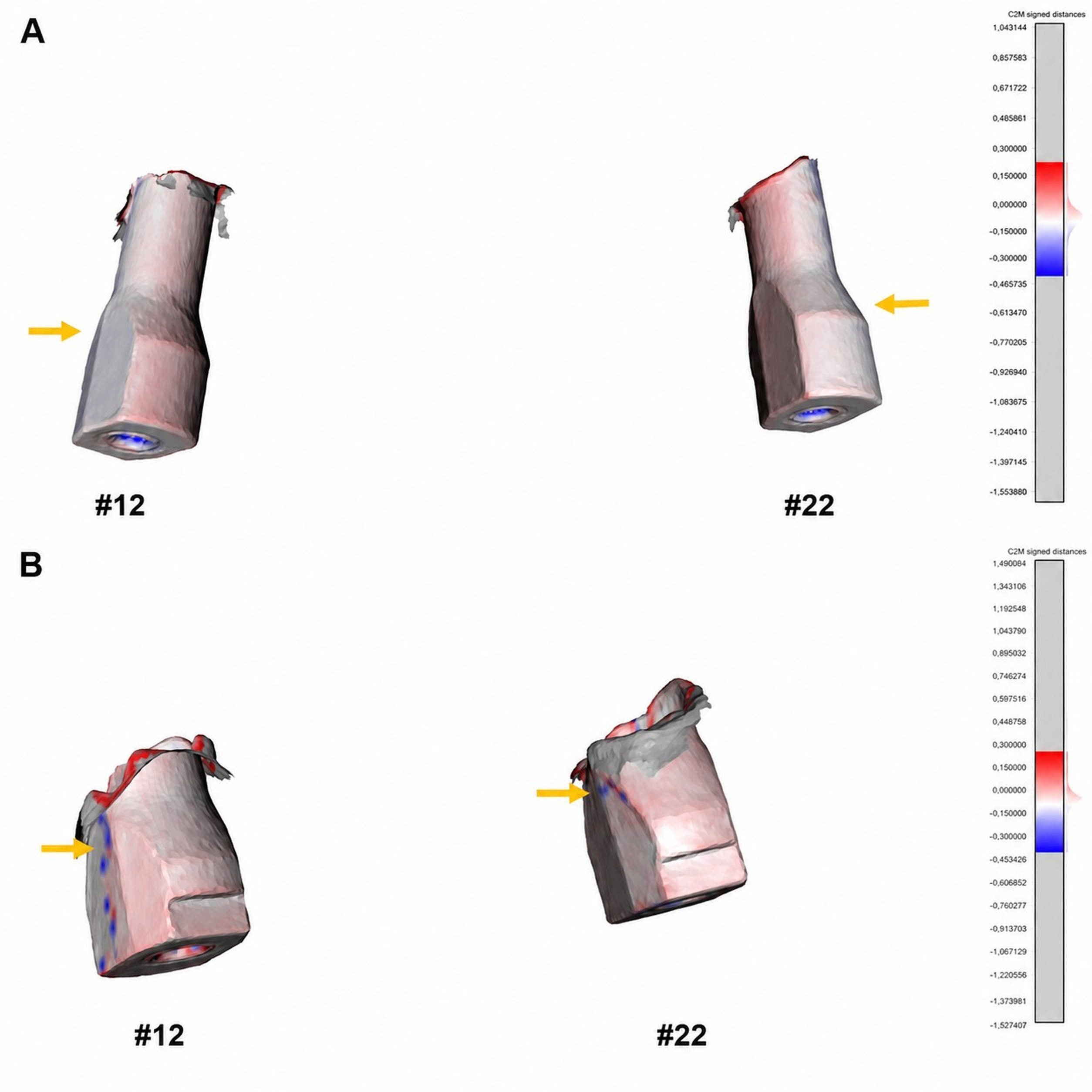
Fig. 3.
Color-coded cloud-to-mesh signed distance maps. The maps compare the IOS dataset with the reference dataset after ICP registration. The color scale was fixed at ±0.300 mm for both panels (blue = −0.300 mm; white = 0 mm; red = +0.300 mm). The yellow arrows indicate representative regions of deviation. (A) Long SB with a predominantly near-zero deviation along the scan body shaft, (B) Short SB with greater deviation along the lateral surfaces. IOS, intraoral scanner; ICP, iterative closest point; SB, scan body.
The LD and AD values obtained from RANSAC-based cylinder fitting are summarized in Table 1 and Fig. 4. At site #12, LD and AD were 0.98 mm and 1.35° in the Long SB condition and 1.17 mm and 2.40° in the Short SB condition, respectively. At site #22, LD and AD were 1.36 mm and 0.34° in the Long SB condition and 1.52 mm and 4.97° in the Short SB condition, respectively. The AD values are plotted against the supragingival SB exposure height in Fig. 5. As only two implant sites were evaluated under each condition, Fig. 5 illustrates the observed values, and no correlation or regression analyses were performed.
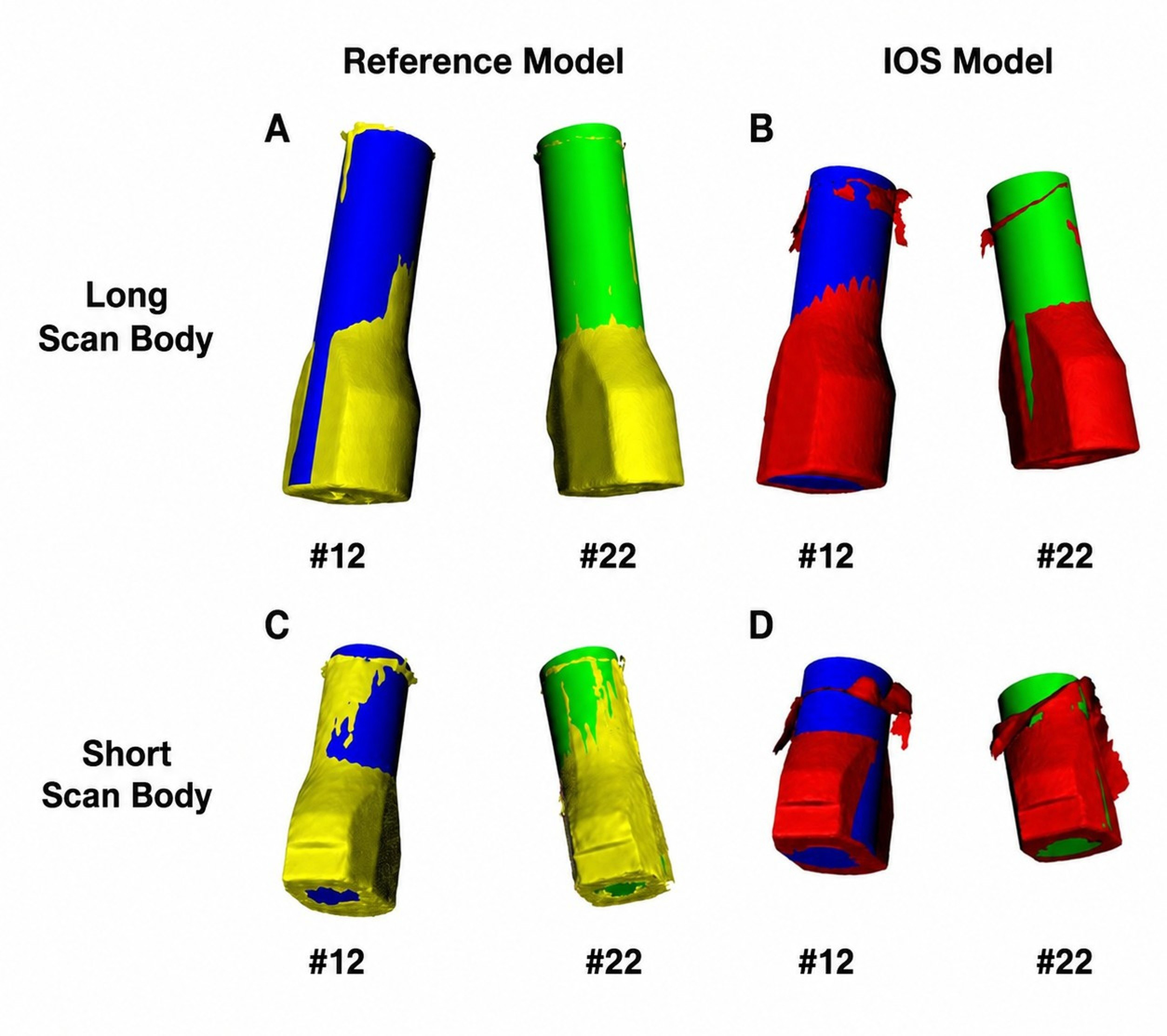
Fig. 4.
RANSAC-fitted cylinder analysis. Virtual cylinders were fitted to the segmented scan body meshes at sites #12 and #22 in each IOS dataset and in the corresponding laboratory-scanned reference dataset generated using the same SB type. (A) Long SB reference dataset, (B) Long SB IOS dataset, (C) Short SB reference dataset, and (D) Short SB IOS dataset. The scan body meshes are shown in yellow (reference) and red (IOS). The fitted cylinders were color-coded according to the implant site: blue, #12; green, #22. IOS, intraoral scanner; RANSAC, random sample consensus; SB, scan body.
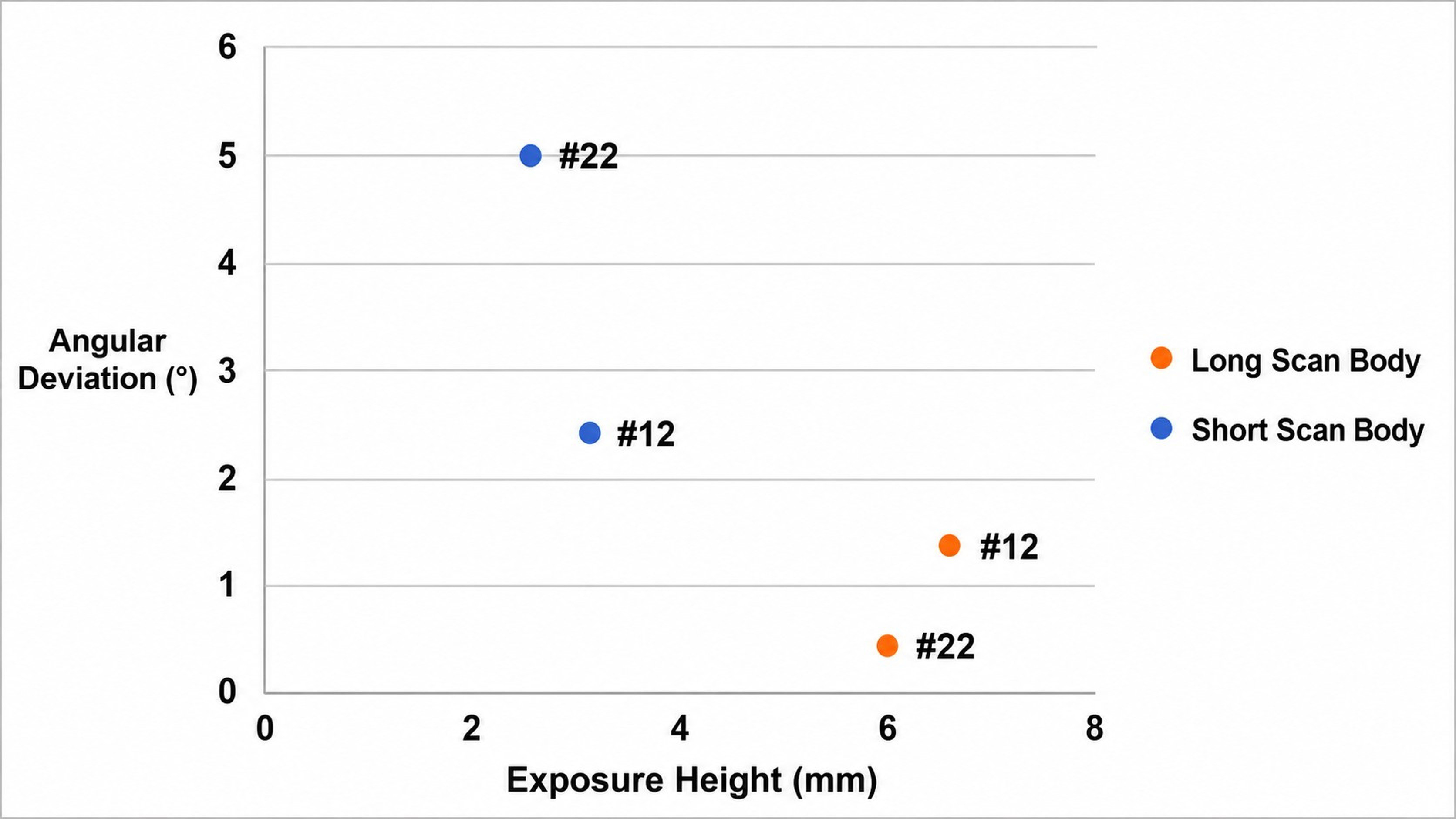
Fig. 5.
Supragingival scan body exposure height and angular deviation for each implant site and scan body condition. Each point represents an implant site under one scan body condition and displays the corresponding supragingival scan body exposure height and angular deviation values. As the analysis was based on a single patient with two implant sites, the figure is presented for descriptive purposes only, and no statistical or inferential analyses were performed.
Ⅳ. Discussion
In this retrospective clinical pilot study, the observed ICP registration RMS error and AD values were numerically higher in the Short SB condition than in the Long SB condition at the evaluated maxillary anterior implant sites. As this report was based on a single patient with two implant sites, these observations should be regarded as preliminary and hypothesis-generating.
Therefore, the LD values observed under both conditions should be interpreted with caution. Because the Short and Long SB datasets were acquired at different clinical stages and compared with condition-specific reference datasets generated from a conventional impression-derived stone cast, cumulative deviations related to soft tissue conditions, SB seating, reference dataset generation, and dataset registration may have influenced the absolute ICP registration RMS error, LD, and AD values. Accordingly, the observed LD difference between conditions should be interpreted descriptively rather than as evidence of a true difference in implant position-transfer accuracy.
The ICP registration RMS error was 29.8 µm for the Long SB dataset and 70.4 µm for the Short SB dataset, representing the residual registration error relative to the reference dataset. The ICP registration RMS error in this study should not be interpreted as direct evidence of passive prosthetic fit or site-specific implant position transfer accuracy. Passive fit refers to the relationship between the implant-supported prosthesis and the implant or abutment interface,14 whereas the ICP registration RMS error represents a dataset-level residual registration metric within a selected overlapping region.
The scanned SB data were matched with the corresponding library file in the CAD software, and the virtual implant position was reconstructed based on this matching process.3 Previous in vitro studies have suggested that the amount of visible SB geometry may affect this process. Jeong et al. reported that greater exposure height of the SB improved library merging accuracy.15 Similarly, Choi et al. found that reduced SB exposure height significantly increased both LD and AD during software-based SB image matching, whereas operator-related differences had limited influence.16 These findings support the possibility that reduced SB exposure height may affect SB recognition and subsequent virtual implant position reconstruction.
Previous studies have reported that the SB exposure height may affect both linear and angular accuracy, although the reported patterns vary. Wu et al. reported that at anterior implant sites, AD showed statistically significant differences when the supragingival SB exposure height was reduced to 6 mm, whereas LD showed statistically significant differences when the exposure height was reduced to 4 mm.9 However, these findings were derived from in vitro settings, and their applicability may vary depending on the study design, implant configuration, SB design, and scanning protocol. In an in vitro complete-arch model, Gómez-Polo et al. reported that implant angulation and supragingival SB exposure height influenced scanning accuracy, with the clearest height-related differences observed in linear discrepancies within the angled implant group.17
In the present dataset, different AD values were observed for the Long SB and Short SB conditions. AD was derived from the axial direction of the fitted SB cylinder. The estimated axial direction depends on the portion of the cylindrical scan body surface available for analysis. Therefore, limited supragingival SB exposure height may affect the stability of the fitted-axis estimation, which may partly explain the observed differences in AD. However, the present study did not statistically compare AD and LD, and the relative sensitivities of these two metrics could not be determined.
Other studies have reported reduced implant position transfer accuracy with decreasing supragingival SB exposure height.10,18 Petchmedyai and Thanasrisuebwong reported that the greatest positional and angular errors occurred when only approximately one-third of the SB image was available, whereas accuracy improved when two-thirds or more was available.10 Nam et al. found that implant position reproduction errors increased as supragingival SB exposure height decreased, with the lowest accuracy observed at the lateral incisor position.18 Because the present study included only two implant sites and no statistical analysis, the relative influence of SB exposure on angular and linear accuracy could not be determined.
However, the influence of the SB exposure height on digital impression accuracy has not been consistently observed in previous studies. Lee et al. reported that Short SBs demonstrated higher surface trueness than regular SBs in mandibular posterior implant models.19 Sicilia et al. also found that supramucosal SB exposure height did not significantly affect intraoral scanning accuracy in most of the comparisons evaluated.20 These differences may be related to several factors, including implant site, implant placement depth, SB design, scanner system, scanning protocol, and the method used to assess accuracy.
Differences in the evaluated implant regions may partly explain the inconsistent findings among studies. At anterior implant sites, scan accuracy may be affected by cumulative stitching errors as the scanning pathway crosses the dental midline. Furthermore, when both maxillary central incisors are missing, the increased edentulous span may reduce the availability of anatomical reference structures, potentially increasing the risk of stitching errors and affecting the SB localization. Wu et al. reported that reduced SB exposure affected the anterior and posterior regions differently, with greater reductions in accuracy observed in the anterior region at higher levels of SB submergence.9
From a practical standpoint, guidance on the minimum supragingival SB exposure height should be based on previous in vitro studies rather than on the present single-patient data. Previous in vitro data suggested that deviation outcomes at anterior implant sites may change when supragingival SB exposure is reduced to approximately 6 mm.9 However, this value should be interpreted as a literature-based reference rather than a validated clinical recommendation. When supragingival exposure is limited, careful verification of the SB capture or supplementation with a conventional impression may be considered.
This study had several limitations. First, the retrospective single-patient design involving only two implant sites precluded statistical analysis, and the findings should be regarded as hypothesis-generating. Second, each SB condition was scanned only once, preventing evaluation of precision and repeatability. Third, the reference datasets were derived from a conventional impression, stone-cast fabrication, and a laboratory scanning workflow. Therefore, they should be considered clinically accepted references rather than error-free gold standards because dimensional deviations may have been introduced during each step of the workflow. Fourth, the Short and Long SB datasets were acquired at different clinical stages, which may have influenced the absolute ICP registration RMS error, LD, and AD values. Finally, the findings are specific to the IOS system, SB design, implant sites, and software workflow used in this case and therefore may not be generalizable to other clinical situations.
Within the limitations of this pilot study, maintaining adequate supragingival SB exposure may be beneficial when performing digital impressions at maxillary anterior implant sites.
Ⅴ. Conclusion
In this retrospective single-patient pilot study, the observed ICP registration RMS error and AD values were numerically lower in the Long SB condition than in the Short SB condition at the maxillary anterior implant sites. Although the findings should be interpreted cautiously because of the limited study design, they suggest that supragingival SB exposure height may be associated with digital implant impression accuracy. Further prospective clinical studies with larger patient cohorts and standardized protocols are needed to clarify the influence of supragingival SB exposure height and identify clinically relevant exposure ranges for maxillary anterior implant digital impressions. Ideally, future studies should fabricate definitive prostheses using both workflows to assess clinically relevant differences besides numerical accuracy.