

Ⅰ. Introduction
Conventional stents manufactured before implant placement are produced on the patient's gypsum model and used as a stent for cone-beam computed tomography (CBCT) imaging before implant placement and after CBCT imaging, which has been modified with a surgical stent and has been used to determine the position of the implant during implant surgery. However, since such a conventional stent is manufactured using a plaster model, the relationship between the implant and the basal bone cannot be accurately identified. In addition, if the difference between the planned implant position and the basal bone after CBCT is significant, it may be necessary to retake CBCT, and during surgery with a modified surgical stent, the stent is used only to mark the position of the implant, and subsequent drilling has a disadvantage in that there may be a slight difference from the planned position and angle of the implant due to a lot of influence on the operator's skill level and the patient factors in the oral cavity. On the contrary, for computer-guideds implant surgical guides manufactured using the computer-aided design-computeraided manufacturing (CAD-CAM) system, prosthodontically-driven plans are established by identifying the relationship between the implant fixture, the basal bone; the upper prosthesis at the stent manufacturing stage and rapid and repetitive manufacturing is possible using a three-dimensional (3D) printer.1
The process of manufacturing a computer-guided implant surgical guide is divided into two parts. The first part is a CAD process. CAD was done using the patient's CBCT and digital information from the teeth. In this process, the clinician can use the program to design the implant position, prosthesis shape, and the surgical guide structure. Alternatively, a manufacturer may design the guide based on patient information, and then a clinician can confirm the production. The second part is the CAM process. Recently, computer-guided implant surgical guides have been manufactured by a 3D printing method, using a light-curing resin. The stereolithography file is produced in the CAD process by a manufacturer to request the production or use a 3D printer in the clinic to manufacture. Digital light processing (DLP) 3D printers with high accuracy and fast production are mainly used.2
Because the position of the drill can be positioned from the start to the end of the drilling during the subsequent surgery, the implant can be accurately placed at the planned position and angle, which is less affected by the operator's skill and patient factors. In addition, flapless surgery, which is mainly used for implant surgery using a computer-guided implant surgical guide, reduces patient swelling and pain and does not have a suture, greatly reducing the patient's postoperative discomfort. Owing to these advantages, computer-guided implant surgical guides using CAD-CAM systems have been widely used in recent implant surgery.3
However, using the computer-guided implant surgical guide, deviations in the implant position and angle may occur depending on the location of the implant to be placed, the length of the implant, and the structure of the computer-guided implant surgical guide. According to a related existing study, the possible mean deviation of 0.67-2.21 mm in the implant apex, 0.46-2.39 mm in the neck, and 1.4-5.9° in the implant angle when using a computer-guided implant surgical guide.4 In addition, flapless surgery using a computer-guided implant surgical guide may affect the occurrence of errors because it is difficult to secure the surgical field of view, and the removal of keratinized gingiva using a punch drill may cause problems in future prosthesis management.3 Therefore, in this literature review, we would like to consider clinical precautions to reduce the implant placement deviation when using a computerguided implant surgical guide.
Ⅱ. Materials and Methods
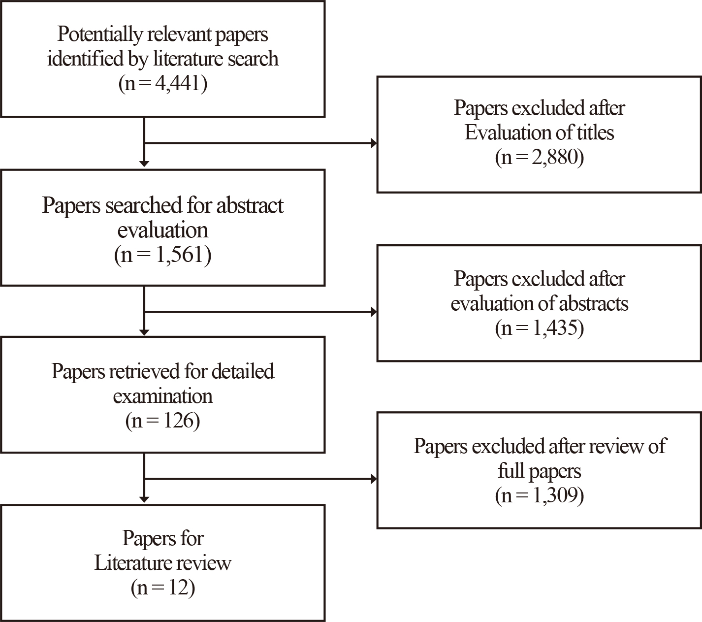
A literature review was conducted to analyze the causes of implant placement deviation. The literature search was first conducted on articles published from 2010 to 2020 in PubMed using guided implant surgery, surgical guide, error, accuracy, and tolerance as search terms {(surgical guide OR guided implant surgery) AND accuracy OR tolerance AND error}. In the first search, 4,441 studies were included. The inclusion criteria were as follows: a static computer-guided implant surgical guide and an implant placed in the oral cavity or a tooth model. In addition, the exclusion criteria were subject to a dynamic navigating system, a bone-supported surgical guide, and an implant that was placed outside the oral cavity, including the zygomatic bone. Based on this criterion, 2,880 papers were excluded from the first 4,441 papers by evaluating the titles. Among the remaining 1,561 papers, 1,435 were exclude after their abstracts were evaluated. After that, the full texts of 126 papers were evaluated and finally, 12 papers were included in the literature review (Fig. 1).
Ⅲ. Results
The 12 papers included in this study are summarized in Table 1. The papers were then divided into four groups according to the variables that analyzed the error of guided implant surgery. The first group (papers 1-5) analyzed the mean deviation (Table 2). The mean deviation was within 1.5 mm on average in the implant neck. In the implant apex, the deviation was within 2.8 mm. Moreover, in the axis, the anlge deviation was within 5.9°. In the vertical deviation, the average was within 1.24 mm, but mostly within 0.5 mm. In general, the deviation in the implant apex was larger than that in the implant neck, and almost no vertical deviation was observed. The second group (papers 6 and 7) verified the deviation according to the implant location (Table 3). The third group (papers 8 and 9) were the deviation according to the drill and sleeve of the computer-guided implant surgical guide (Table 4). As the distance from the sleeve to the bone increased and the sleeve diameter increased, the deviation increased. In addition, as the height of the sleeve increased and the length of the drill increased, the deviation decreased. The fourth group (papers 10, 11, and 12) verified the error according to the implant system, the number of residual teeth and the type of 3D printer (Table 5). The deviations of several implant systems used in guided implant surgery were within the clinically acceptable range. In the deviation related to residual teeth, when the computer-guided implant surgical guide was supported in at least four teeth, no significant difference in accuracy was observed compared to obtaining support in the teeth. Also, when the computer-guided implant surgical guide was supported in the posterior region, the accuracy increased. Regarding the type of 3D printer, CON (Objet Eden260VS; Stratasys, Eden Prairie, MN, USA) and D1 (D1; Veltz3D, Incheon, Korea) showed superior internal adaptation with a gap distance of less than 1 mm. The mean degree of diversion of the guide holes ranged from 3.45° for ZEN (Zenith U; Dentis, Daegu, Korea) to 6.55° for PER (Perfactory Micro Advantage; EnvisionTEC, Dearborn, MI, USA). The tolerances of CON (4.70°) and D1 (4.50°) did not differ significantly.
Table 1.
Summary of the included studies
| No | Title | Year | Author | Variables |
| 1 |
Accuracy of computer-aided template-guided oral implant placement a prospective clinical study | 2014 | Beretta M et al. | Deviation |
| 2 | Guided implant surgery risks and their prevention | 2019 | Tatakis DN et al. | Deviation |
| 3 | Is digital guided implant surgery accurate and reliable? | 2019 | Al Yafi F et al. | Deviation |
| 4 |
CAD/CAM implant surgical guides: maximum errors in implant positioning attributable to the properties of the metal sleeve/osteotomy drill combination | 2018 | Apostolakis D et al. | Deviation |
| 5 | Accuracy of computer‐aided implant placement | 2012 | Van Assche N et al. | Deviation |
| 6 |
Stereolithographic surgical guide with a combination of tooth and bone support: accuracy of guided implant surgery in distal extension situation | 2020 | Lin CC et al. | Implant location |
| 7 |
Accuracy of implant surgery with surgical guide by inexperienced clinicians an in vitro study | 2015 | Toyoshima T et al. | Implant location |
| 8 |
Tolerance within the sleeve inserts of different surgical guides for guided implant surgery | 2013 | Koop R et al. |
Sleeve length, diameter |
| 9 |
In‐vitro evaluation of the tolerance of surgical instruments in templates for computer‐assisted guided implantology produced by 3D printing | 2015 | Schneider D et al. |
Sleeve diameter, Dill length, Drill key |
| 10 |
Accuracy and precision of 3D-printed implant surgical guides with different implant systems: An in vitro study | 2020 | Yeung M et al. | Implant system |
| 11 |
Influence of surgical guide support and implant site location on accuracy of static computer-assisted implant surgery | 2019 | El Kholy K et al. | Residual teeth |
| 12 | Assessment of metal-sleeve free 3D printed implant surgical guide | 2019 | Oh KC et al. | Type of 3D printer |
Table 2.
Studies summarizing associated with implant deviation used a computer-guided implant surgical guide
| No | Author | Cited article | Deviation |
| 1 | Beretta M et al., 2014 | Implant neck (head): 0.56 mm | |
| Implant apex: 0.64 mm | |||
| Axis(angle): 2.42° | |||
| 2 | Tatakis DN et al., 2019 | Van Assche N et al., 2012 and Tahmaseb et al., 2014 | Implant neck (head): 1.0~1.2 mm |
| Implant apex: 1.2~1.39 mm | |||
| Axis(angle): 3.8° | |||
| Vertical: 0.5 mm | |||
| Vercruyssen M et al., 2014 | Implant neck (head): 1.4 mm | ||
| Implant apex: 1.6 mm | |||
| Axis(angle): 3.0° | |||
| 3 | Al Yafi F et al., 2019 | Tahmaseb et al., 2018 | Implant neck (head): 0.9~1.3 mm |
| Implant apex: 1.2~1.5 mm | |||
| Axis(angle): 3.3°~3.5° | |||
| Vertical: 0.2~0.5 mm | |||
| Zhou et al., 2018 | Implant neck (head): 1.22~1.29 mm | ||
| Implant apex: 1.53~1.62 mm | |||
| Axis(angle): 3.97°~4.23° | |||
| Vertical: 0.64~1.24 mm | |||
| Bover-Ramos et al., 2018 | Implant neck (head): 0.77~1.18 mm | ||
| Implant apex: 0.17~1.52 mm | |||
| Axis(angle): 2.39°~2.82° | |||
| Vertical: 0.28~0.61 mm | |||
| 4 | Apostolakis D et al., 2018 | Implant neck (head): 0.1~1.5 mm | |
| Implant apex: 0.1~2.8 mm | |||
| Axis(angle): 0.4°~5.9° | |||
| Vertical: 0.0~0.1 mm | |||
| 5 | Van Assche N et al., 2012 | Implant neck (head): 0.99 mm | |
| Implant apex: 1.24 mm | |||
| Axis(angle): 3.81° | |||
| Vertical: 0.46 mm |
Table 3.
Studies summarizing associated with implant deviation about implant location
| No | Author | Implant location | Deviation |
| 6 | Lin CC et al., 2020 | #36 | 0.24 ± 0.25 mm |
| #46 | 0.21 ± 0.14 mm | ||
| #47 | 0.43 ± 0.19 mm | ||
| 7 | Toyoshima T et al., 2015 | #45 | 1.41 ± 0.39 mm |
| #47 | 2.61 ± 0.46 mm |
Table 4.
Studies summarizing associated with implant deviation about the sleeve of a computer-guided implant surgical guide
| No | Author | Variables | Deviation | ||
| 8 | Koop R et al., 2013 |
Sleeve – bone distance (drill hold sleeve insert, osteotomy depth 8mm, diameter 2.0 drill) | 3 mm |
neck: 0.6 mm, apical: 1.1 mm, angle: 2.7° | |
| 5 mm |
neck: 1.0 mm, apical: 1.4 mm, angle: 3.7° | ||||
| 7 mm |
neck: 1.1 mm, apical: 2.0 mm, angle: 6.9° | ||||
| 9 mm |
neck: 1.5 mm, apical: 2.3 mm, angle: 7.0° | ||||
|
Sleeve insert height (osteotomy depth 8 mm, diameter 2.0 drill) | 5 mm |
neck: 0.7 mm, apical: 1.0 mm, angle: 3.0° | |||
| 8 mm |
neck: 0.3 mm, apical: 0.4 mm, angle: 1.2° | ||||
|
Sleeve insert diameter (osteotomy depth 8 mm, 5 mm distance) | 3.2 mm |
neck: 0.8 mm, apical: 1.3 mm, angle: 3.3° | |||
| 3.3 mm |
neck: 1.2 mm, apical: 1.9 mm, angle: 4.8° | ||||
|
Sleeve height (osteotomy depth 8 mm, diameter 2.0 drill) | 3 mm |
neck: 1.0 mm, apical: 1.5 mm, angle: 3.8° | |||
| 5 mm |
neck: 0.8 mm, apical: 1.1 mm, angle: 2.9° | ||||
| 7 mm |
neck: 0.6 mm, apical: 0.7 mm, angle: 1.1° | ||||
| 9 mm |
neck: 0.6 mm, apical: 0.8 mm, angle: 1.4° | ||||
| 9 | Schneider D et al., 2015 | Drill length | sleeve ∅ 4.7 | 18 mm (1 mm drill key) | lateral movement: 0.76 mm |
| 25 mm (1 mm drill key) | lateral movement: 1.04 mm | ||||
| sleeve ∅ 45.0 | 16 mm (1 mm drill key) | lateral movement: 0.76 mm | |||
| 24 mm (1 mm drill key) | lateral movement: 1.34 mm | ||||
| Drill key | sleeve ∅ 4.7 | 1 mm (25 mm drill length) | lateral movement: 1.04 mm | ||
| 4 mm (25 mm drill length) | lateral movement: 0.79 mm | ||||
| sleeve ∅ 45.0 | 1 mm (24 mm drill length) | lateral movement: 1.34 mm | |||
| 3 mm (24 mm drill length) | lateral movement: 1.00 mm | ||||
Table 5.
Studies summarizing associated with implant deviation about implant systems and residual teeth
| No | Author | Variables | Deviation | |
| 10 | Yeung M et al.,2020 | Implant systems |
BioHorizons (BH) | M (mesial): 0.06 mm |
| VMD (vertical in mesiodistal): -0.21 mm | ||||
| ALP (angle in labiopalatal): 1.86° | ||||
|
Nobel Biocare (NB) | M (mesial): -0.03 mm | |||
| VMD (vertical in mesiodistal): 0.35 mm | ||||
| ALP (angle in labiopalatal): 2.05° | ||||
|
Zimmer Biomet (ZB) | M (mesial): -0.09 mm | |||
| VMD (vertical in mesiodistal): 3.46 mm | ||||
| ALP (angle in labiopalatal): 0.77° | ||||
| 11 | El Kholy K et al.,2019 |
Residual teeth (used for surgical guide stent support) | Full arch | crest: 0.284 mm, apex: 0.675 mm, angle: 4.363° |
| 4-teeth | crest: 0.289 mm, apex: 0.616 mm, angle: 4.731° | |||
| 3-teeth | crest: 0.562 mm, apex: 1.195 mm, angle: 5.688° | |||
| 2-teeth | crest: 1.015 mm, apex: 1.657 mm, angle: 7.713° | |||
| 12 | Oh KC et al.,2019 | Type of 3D printer |
Objet Eden260VS (CON) |
CON and D1 showed superior internal adaptation with a gap distance of less than 1mm. The mean degree of diversion of the guide holes ranges from 3.45° for ZEN to 6.55° for PER. The tolerances of CON (4.70°) and D1 (4.50°) did not differ at the level of statistical significance. |
|
D1 (D1) | ||||
|
Form2 (FOR) | ||||
|
OneJet (ONE) | ||||
|
Perfactory Micro Advantage (PER) | ||||
|
Zenith U (ZEN) | ||||
Ⅳ. Discussion
The mean deviation of the guided implant surgery was analyzed in the first group. Beretta M et al. analyzed deviations in flapless implant surgery using a computer-guided implant surgical guide.5 As a result, the average deviation was 0.56 mm in the implant neck, 0.64 mm in the implant apex, and 2.42° in the axis. Tatakis DN et al. analyzed various studies on the accuracy, referring to the risk of guided implant surgery.6 As a result, the deviation was 1.0-1.2 mm in the implant neck, 1.2-1.39 mm in the implant apex, and 3.8° in the axis, and the vertical deviation was reported as 0.5 mm. Futhermore, when the guided implant surgery was performed on fully edentulous patients, the average deviation was reported to be 1.4 mm in the implant neck, 1.6 mm in the implant apex, and 3.0° in the axis. Similarly, Al Yafi F et al. analyzed a few studies regarding deviations in guided implant surgery.7 As a result, the deviation range was 0.77-1.3 mm in the implant neck, 0.17-1.62 mm in the implant apex, and 2.39-4.23° in the axis, and the vertical deviation was 0.2-1.24 mm. Apostolakis et al. reported that when a computer-guided implant surgical guide was used, the deviation of the implant was 0.4-5.9° in the axis, 0.1-1.5 mm in the neck, 0.1-2.8 mm in the apex, and 0-0.1 mm in the vertical.8 In addition, Van Assche et al. reported in a meta-analysis that when using a computer-guided implant surgical guide, the deviation was measured as an average of 3.81° in the axis, 0.99 mm in the neck, 1.24 mm in the apex, and 0.46 mm in the vertical.9 As a result, it was found that implant displacement may occur during implant placement using a computer-guided implant surgical guide. The extent was greater at the implant apex than at the implant neck. The values were within 1.5 mm at the implant neck and within 2.8 mm at the implant apex, and the angle deviation was within 5.9°. Therefore, it should be recognized that even when an implant is placed using a computer-guided implant surgical guide, a deviation in the implant may occur. Addtionally, since the deviation may increase in the implant apex, a sufficient safety margin should be secured to prevent damage to the anatomical structures at the apex region, such as the inferior alveolar nerve and maxillary sinus floor.
In the second group, deviation according to implant location was analyzed. Lin CC et al. placed implants in the mandibular left first molar (#36i) and mandibular right first and second molars (#46i and 47i) using a computer-guided implant surgical guide, the largest deviation was observed in the implant placed at the rearmost position, especially at the second molar.10 The values were #36i (0.04 ± 0.25 mm), #46i (0.21 ± 0.14 mm), and #47i (0.43 ± 0.19 mm). Also, Toyoshima et al. reported that when comparing the mandibular right second premolar and second molar implants (#45i and 47i), a larger angular deviation occurred in the rearmost implant (#47i) with the values of 2.10° ± 2.2° (#45i) and 5.46° ± 2.09°(#47i).11 Therefore, it was found that a larger deviation may occur in the posterior implant when the implant is placed using a computer-guided implant surgical guide. In particular, in the distal extension situation, deviations may occur due to insufficient stability, therefore, it is necessary to add a strut that can obtain additional support to the mucosa or bone to the stent structure.
In the third group, the deviation according to the drill and sleeve of the computer-guided implant surgical guide was analyzed. Koop et al. reported that the deviation in guided implant surgery using a computer-guided implant surgical guide is related to the length and diameter of the sleeve.12 It was said that the deviation increases as the distance between the sleeve and the bone of the computer-guided implant surgical guide increases and the diameter of the sleeve increases. Also, if the distance between the sleeve and the bone was more than 7 mm, a significant deviation in the placed implant was observed. In addition, the deviation decreased as the height of the sleeve and the height of the sleeve insert increased. Schneider et al. reported that the length of the drill key and the drill inserted into the sleeve were involved in the deviation and that a short drill length and a long drill key reduced the deviation.13 Therefore, to reduce the deviation, the computer-guided implant surgical guide should be designed to have a sufficient sleeve length to prevent lateral movement even if the length of the drill key increases. Moreover, if the thickness of the soft tissue at the implant site is 7 mm or more, flapless implant placement using a computer-guided implant surgical guide should be avoided. In addition, considering the length of the implant to be placed and the patient's intermaxillary distance, surgery should be performed using a drill with the minimum length.
In the fourth group, the relationship between the manufacturer, the number of residual teeth, the type of 3D printer, and the deviation were analyzed. Yeung et al. reported that when the computer-guided implant surgical guide of three implant systems was used, the deviations were within the clinically acceptable, with the mesiodistal < 0.1 mm, labiolingual 0.5-1.0 mm, angulation 1-2°, and vertical displacement 2.0-3.0 mm.14 El Kholy et al. studied the relationship between the number of residual teeth and deviation. It was said that if at least 4 residual teeth were supporting the computer-guided implant surgical guide, there was no significant difference in the accuracy with the computer-guided implant surgical guide supported in all the teeth.15 Oh KC et al. compared the computer-guided implant surgical guide (CON) manufactured by an implant company (Osstem, Busan, Korea) with the computerguided implant surgical guide (D1, FOR, ONE, PER, ZEN) manufactured by 5 types of in-office 3D printers.16 None of the 3D printers fabricated superior implant surgical guides to those produced by the manufacturer with regard to the internal fit and guide tolerance. However, the potential for the routine clinical use of in-office 3D printers has been demonstrated. Therefore, it was found that the type of 3D printer used to manufacture the computer-guided implant surgical guide or implant system used during surgery did not affect the implant deviation. However, the number of residual teeth supporting the computer-guided implant surgical guide can affect accuracy. Therefore, the computer-guided implant surgical guide should be designed to obtain support from at least four teeth, and if support cannot be obtained from at least four teeth, an anchor pin that can fix the stent during surgery should be used.
Ⅴ. Conclusion
Deviations in guided implant surgery using a computer-guided implant surgical guide can occur due to various factors. Based on the literature review, the clinical precautions in guided implant surgery using a computer-guided implant surgical guide are as follows.
(1) Even if a computer-guided implant surgical guide is used, deviations in the implant position may occur. In particular, a greater deviation may occur when placing an implant in the posterior location using a distal extension computer-guided implant surgical guide. Therefore, it is necessary to secure a sufficient anatomical safety margin when placing the posterior implants.
(2) When manufacturing a computer-guided implant surgical guide, it should be designed to have a sleeve height that is sufficiently longer than the length of the drill key used. In addition, a minimum length drill should be used in consideration of the sleeve, the implant length to be placed, and the patient's intermaxillary distance.
(3) The thickness of the soft tissue at the site should be less than 7 mm, so the gap between the lowest point of the sleeve and the bone should be reduced. If the soft tissue thickness is more than 7 mm, flapless implant placement using a computer-guided implant surgical guide should be avoided.
(4) The computer-guided implant surgical guide must be supported by at least four teeth, and if support cannot be obtained from up to four teeth, use an anchor pin that can fix the stent during guided implant surgery.
