

Ⅰ. Introduction
Placing implants in an optimal position is important for the functional and aesthetic success of fixed implant restorations. Prosthesis-driven implant placement using a surgical guide,1 which is a surgical approach to planning and placing dental implants based on the final prosthesis, has been mentioned since the mid-1980s.2 Properly planned implant surgery minimizes the surgical risk of maxillary sinus perforation, dehiscence, fenestration, and mandibular nerve damage and ensures proper positioning while preventing contact with adjacent implants or adjacent teeth.3,4 The emergence profile of prostheses to be manufactured in the future can be evaluated in advance using software.5 Guide-based surgery has advantages in almost all cases because implants can be placed exactly in the planned position; however, it is especially useful for completely edentulous patients, for placing multiple consecutive implants, and when important anatomical structures are nearby.6
Guides for implant surgery are divided into tooth support, soft tissue support, and bone support according to the anatomic structure used to obtain support. Bone-support surgical guides have limited use owing to their poor accuracy and practicality. In general, tooth-supported surgical guides are used for partially edentulous jaws, and soft-tissue-supported surgical guides are used for fully edentulous jaws.5 Additionally, in the case of soft tissue support, the position of the guide can be fixed using a screw or pin to stabilize the guide.
There is a difference in the guide manufacturing method between partially and completely edentulous patients. In partially edentulous patients, after an optical scan of the patient's model or actual oral cavity, a Cone Beam Computed Tomography (CBCT) scan is superimposed to produce a guide that fits the actual patient's tissue. In the case of completely edentulous patients, the dual-scan method is used because the model scan data and CBCT data cannot overlap due to the absence of teeth. The dual-scan method is a method in which CBCT is taken while wearing dentures for radiography; dentures are taken separately, and then the two sets of data are overlapped to produce a guide.7 The dual-scan method copies the inside of the denture instead of creating a guide that fits the mucosa of the patient.
This case report is about a case in which a guide was fabricated by the "dual optical scan method" using two optical scan models in a situation where CT data and model scan data were not suitable.
Ⅱ. Case report
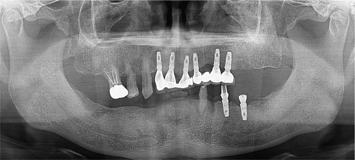
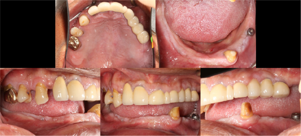
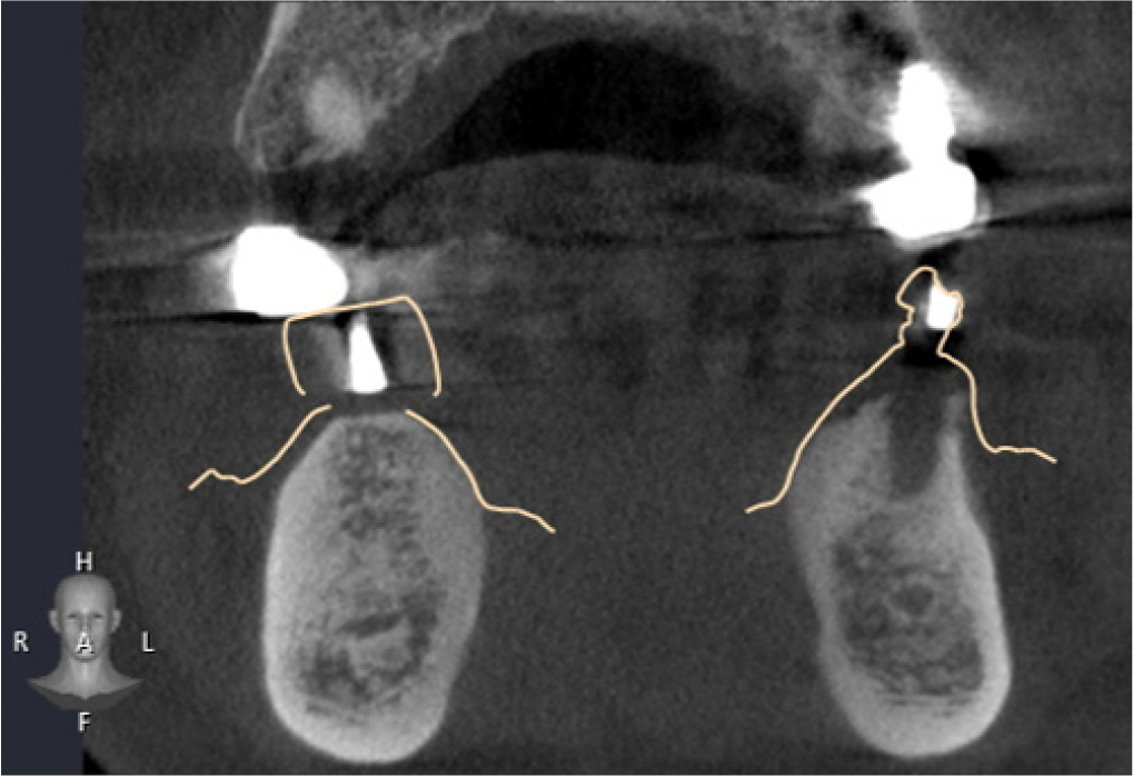
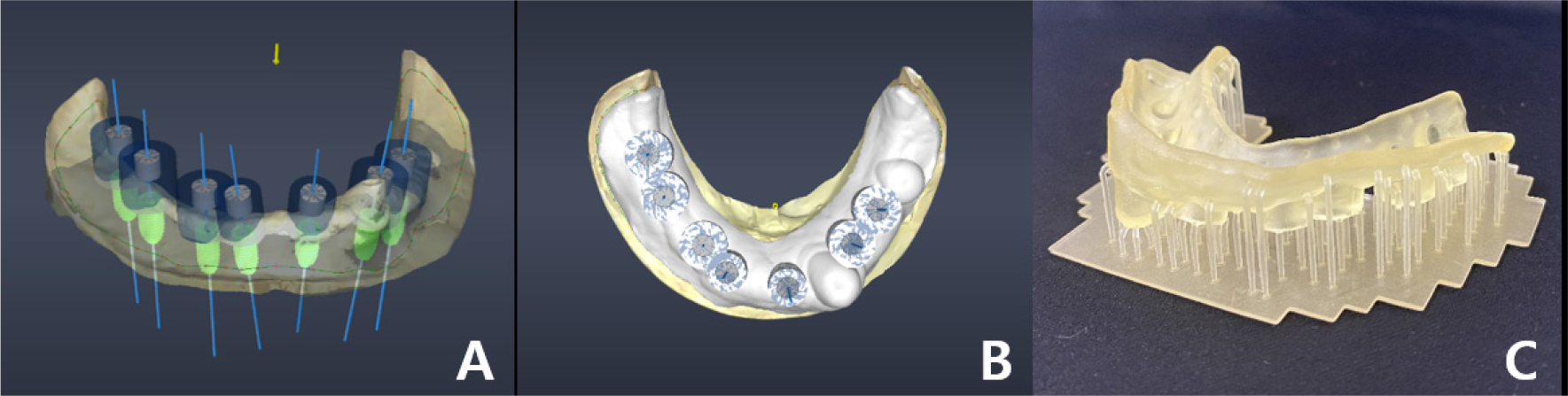
A 58-year-old male patient visited our hospital with chief complaints of missing mandibular teeth. The patient had hypertension and hyperlipidemia. Clinical and radiological examinations revealed multiple tooth loss in the mandible and canting of the maxillary teeth. The implant in the lower left second premolar area showed degree II mobility and vertical bone loss around the fixture, indicating a loss of osseointegration (Figs. 1 and 2). After removal of the dental implant on #35, implant placement was planned at sites #47, 46, 44, 43, 32, 33, 34, 36, and 37. The patient refused to undergo temporary denture placement. A radiographic stent was fabricated after bite registration using a record base, which is the conventional method for fabricating a stent in a partially edentulous jaw. CBCT was taken, and the stone model was scanned using an optical scanner (Medit T500 Dental 3D Scanner; Medit Corp., Seoul, Korea) (Fig. 3A).
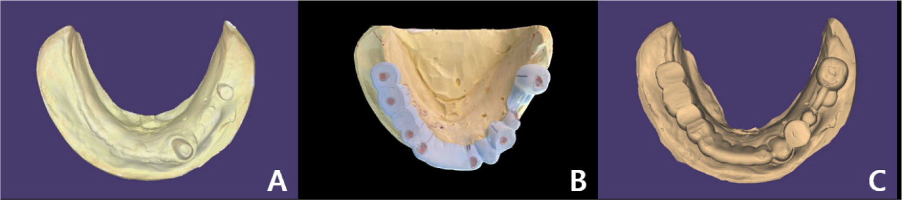
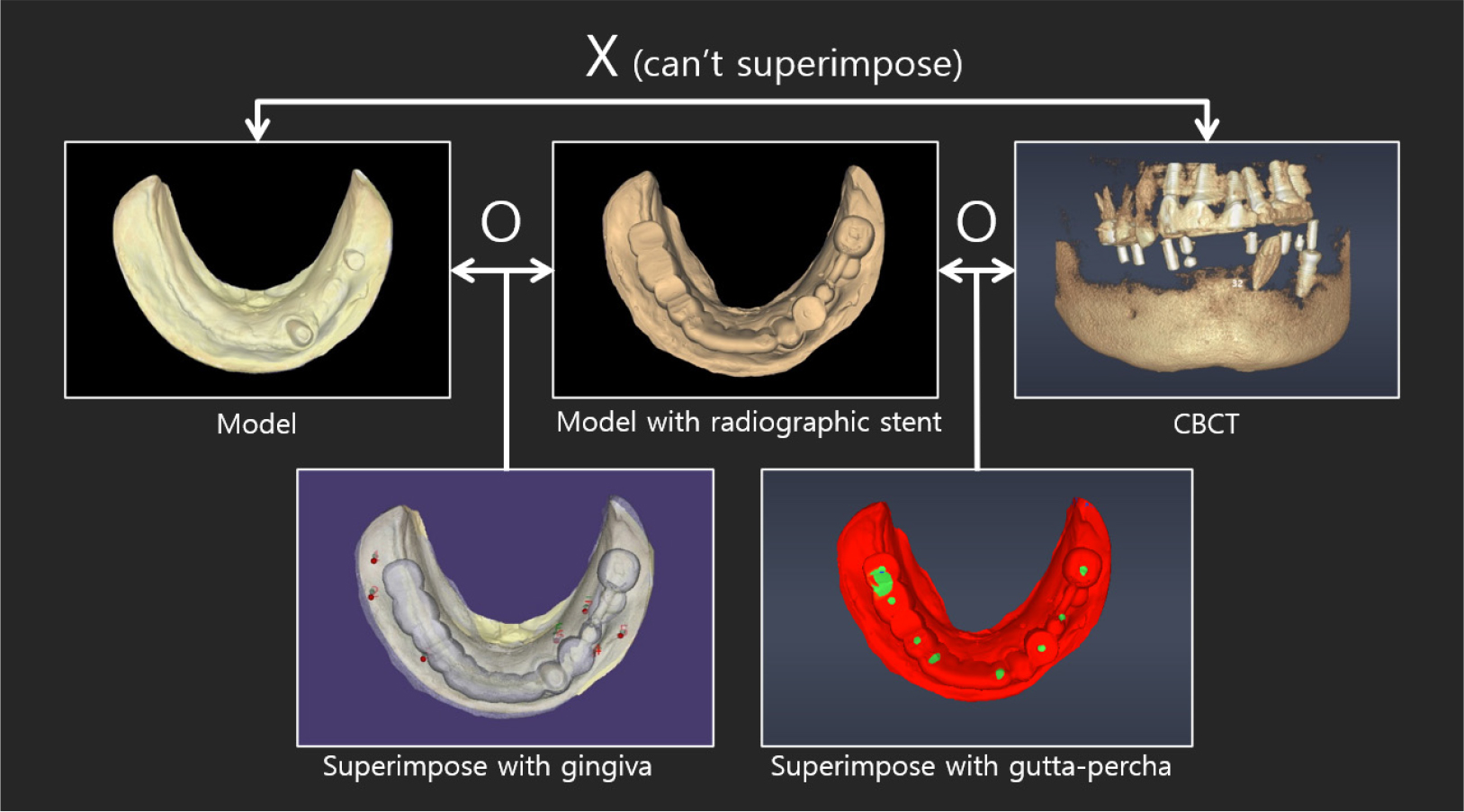
The model and CT scan data were superimposed using a dedicated software (DentiqGuide; 3D Industrial Imaging Co., Ltd., Seoul, Korea) for guided surgery and treatment planning. However, the mandibular arch had one tooth and one healing abutment on one side, which was not properly superimposed. Based on previous experience, it was thought that superimposition would be possible with 2-3 remaining teeth; therefore, the part where additional radiographic markers were not attached became a problem. To solve this problem, after applying powder (VITA powder scan spray; VITA Zahnfabrik H. Rauter GmbH & Co., KG, Bad Säckingen, Germany) to the radiographic stent and placing it on the stone model, an optical scan was performed to create another STL file (Fig. 3B and 3C).
DentalCAD 2.3 (Exocad GmbH; Darmstadt, Germany) program was used to superimpose radiographic stent model scan data with model scan data, and then both files were loaded on DentiqGuide software. DICOM files from CBCT data and radiographic stent model scan data were superimposed on DentiqGuide software using gutta-percha (Temporary stopping; GC Corporation, Tokyo, Japan) to match the model scan data with CBCT data (Fig. 4). In addition, to confirm that the model scan data and CBCT data matched accurately, we checked whether the gingiva line of the model and the bone line of CBCT matched the software and whether the location of the gutta-percha in the model and CBCT matched (Fig. 5). Implant planning and surgical guide design were performed by referring to the CBCT and model scan data, and the surgical guide was printed using a DLP (Digital Light Processing) type 3D printer (Zenith D; Dentis, Daegu, Korea) (Fig. 6). The lower left canine root is tilted mesially. Therefore, when working with the planning software, placing the implant on the adjacent lateral incisor was difficult, and the cantilever was planned after placement on the central incisor.
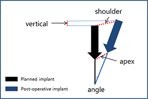
Guided surgery was performed using a Dentium guide kit (XGSFK; Dentium, Seoul, Korea) for implant placement at positions #47, # 46, # 44, # 43, and # 31. To overcome the limitations of the tissue- supported guide and increase accuracy, the tops of the implants and crest levels were checked through minimal flap formation (Fig. 7). After implant placement, CBCT was taken, and the DICOM file was registered in the implant planning software (DentiqGuide; 3D Industrial Imaging Co.,Ltd., Seoul, Korea), and automatically calculated error values were obtained through the ‘pre- and post-operative analysis’ function in the software (Table 1).
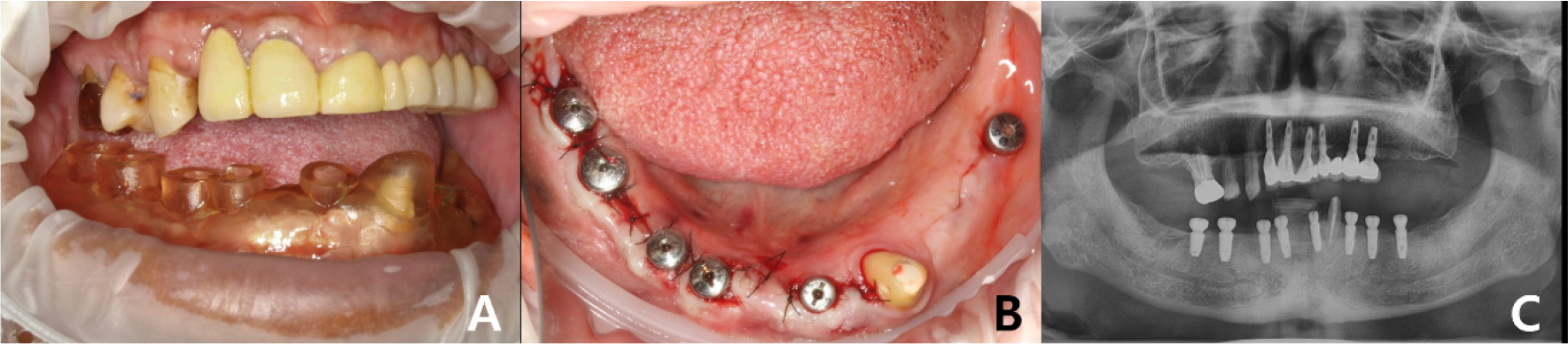
Table 1.
Comparison information between the planned implant and the post-operative implant. Angle: angle difference; shoulder: distance between the tops of implants; apex: distance between the bottoms of implants; vertical: depth difference (if the embedded implant is placed deeper than the planned implant, it is considered positive)
 | #47 | #46 | #44 | #43 | #32 | ||
| Angle | 8.6° | 4.0° | 0.6° | 0.5° | 3.6° | ||
| Shoulder | 1.71mm | 1.42mm | 0.83mm | 1.08mm | 0.57mm | ||
| Apex | 1.83mm | 1.21mm | 0.90mm | 1.14mm | 0.96mm | ||
| Vertical | ‒1.16mm | 0.18mm | ‒0.40mm | ‒0.12mm | ‒0.32mm |
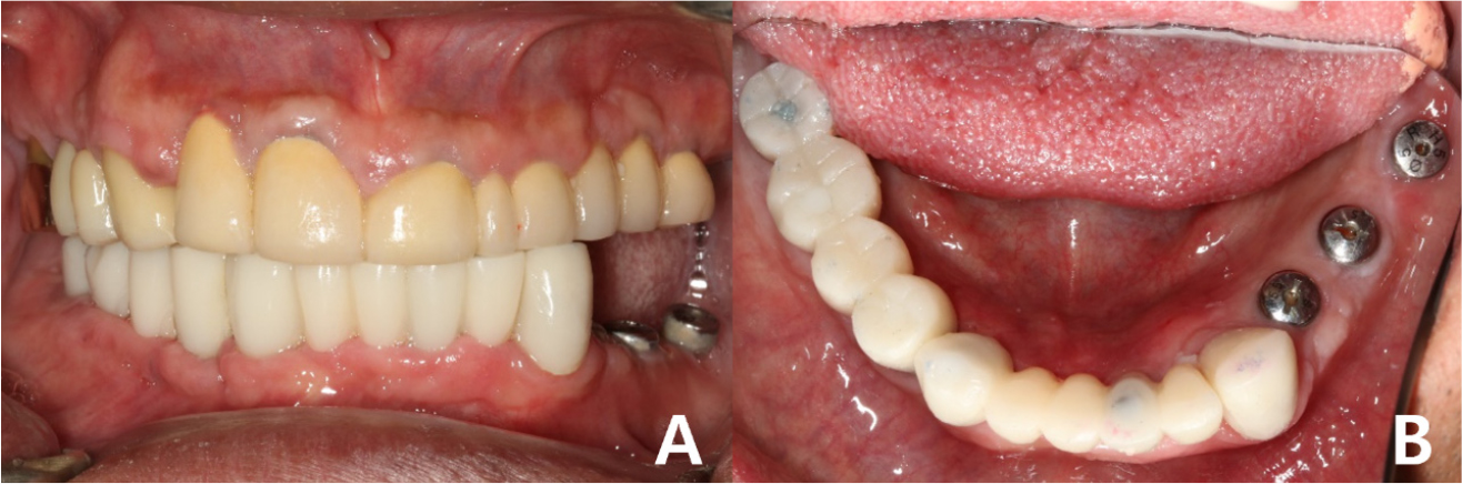
Provisional fixed implant prostheses were placed after the healing period (Fig. 8). The final prostheses were planned to be completed after verifying the vertical dimensions and occlusion using the provisional prostheses.
Ⅲ. Discussion
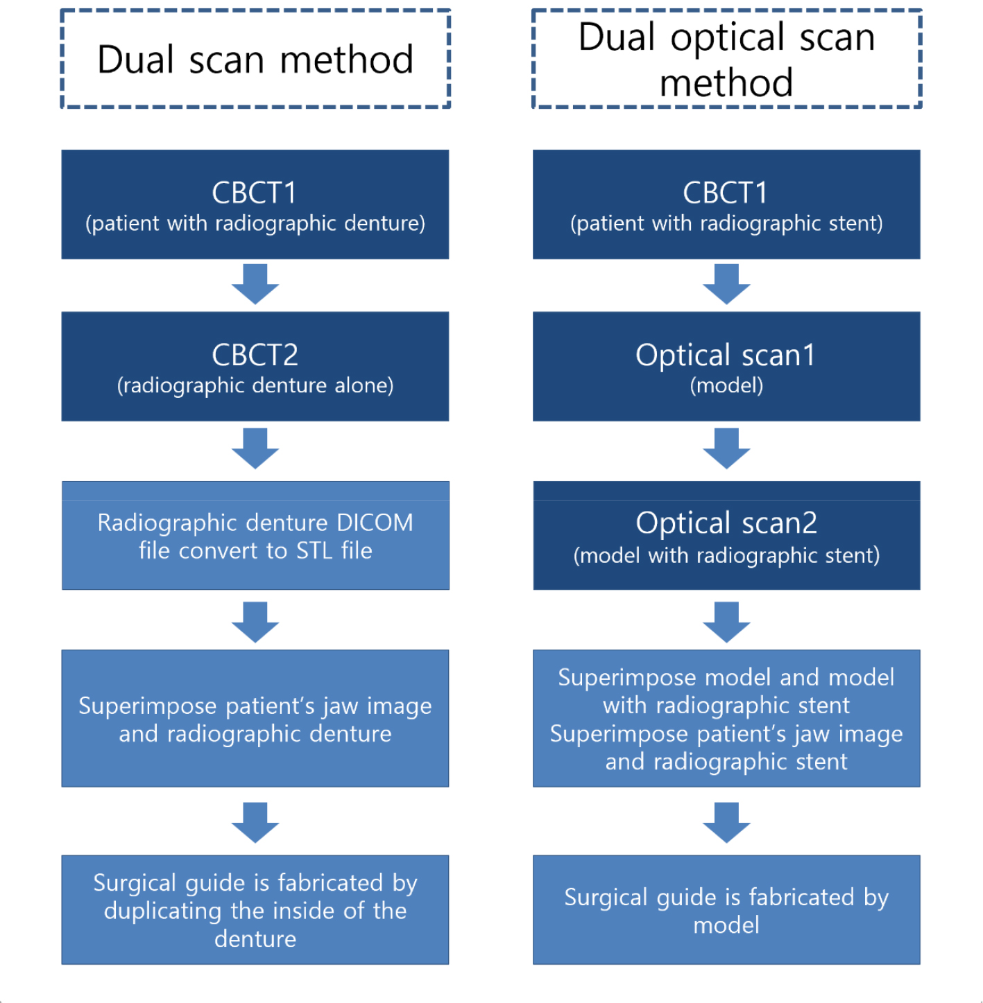
In this case, a guide was fabricated using only one tooth and one healing abutment on one side of a partially edentulous patient. Even in the presence of residual teeth, it is difficult to superimpose CBCT and model data if they exist only on one side, and it is advantageous to superimpose when there is at least one tooth on both sides.8 If there are an insufficient number of teeth to fit the CBCT data, the dual-scan method is commonly used. However, in this case, a denture-type radiographic stent, which is used in the standard dual-scan method, was not used. CBCT had already been performed because it was thought that one tooth and one healing abutment would be suitable for the superimposition process. Therefore, the patient needed to return to the hospital for the dual scan method. The dual-scan method requires not only the fabrication of a denture-type radiographic stent but also CBCT scan data with the stent (due to the difference in the location of the gutta-percha of the radiographic denture to be made and the gutta-percha of the already taken CT). A dual optical-scanning method was devised to avoid additional patient visits (Fig. 9).
The advantage of the method using a non-denture-type radiographic stent is, first, that errors in the manufacturing process are eliminated as the process of manufacturing the denture is eliminated. In the previous method, the guide was manufactured using CBCT data of the inner surface of the denture. However, when it was manufactured in this way, errors occurred in the guide as much as the error in the denture manufacturing process. It is possible to manufacture a surgical guide that is better suited to a patient's tissue by directly using model scan data. In addition, errors occur during the process of converting DICOM files into STL files,9 and these errors can be eliminated.
Secondly, the process of using a denture with CBCT can be omitted. In the dual CBCT scan method, there is a CBCT process of the denture alone; therefore, the CBCT equipment must be used twice. However, this method does not involve this process.
One disadvantage of this method is that superimposition is difficult using gutta-percha alone. On a radiographic stent, the gutta-perchas are exposed as only one plane on the occlusal plane, which may be difficult to match with a point. In this case, this was possible because there were enough gutta-perchas; however, superimposition would not work well if there were not many gutta-perchas. To solve this problem, adding more radiopaque markers to the buccal and lingual sides of the radiographic stent before CBCT imaging will facilitate superimposition.
In this case, it was difficult to ensure perfect superimposition because there were insufficient markers other than gutta-percha. Because the accuracy of superimposition is the key to the precision of guided surgery, a process to reconfirm it is needed. In the superimposed CBCT cut view of the radiographic stent model scan and CBCT data, the fit of the thin part of the gingiva was checked, and it was confirmed that there was no place where the boundary of the bone deviated from the boundary of the model in all parts. In addition, the gutta-percha in the CBCT data coincided with that in the optical model scan data. One limitation of this method is that it cannot be used unless there is a function to load additional optical scan data into the guide design software.
In the postoperative comparison data, the closer the implant was to the residual tooth, the closer the implant position and placement angle were to the planned position, and the error increased as the implant moved further toward the distal end. According to a study on the accuracy of guided surgery by Tahmaseb et al.,10 in the case of edentulous patients, the average error at the top of the implant was 1.3 mm, and in the apex, it was 1.5 mm and the angle was 3.3 degrees. Although most of the data recorded errors close to the average, it could be said to be successful; #47i, the rearmost implant, recorded data that were out of the average. A large error of 8.6° was observed at this angle. This is thought to be due to the low stability of soft tissue support in the form of a distal extension base. To overcome this, the surgical guide was extended bilaterally to the buccal shelf and retromolar pad. In #47i, the implant length was planned to be 10 mm; however, 8 mm was actually placed, and it was measured using the software to be larger than the actual difference in the shoulder, apex, and vertical, resulting in a high value.
Ⅳ. Conclusion
In this case, a surgical guide was fabricated using the dual optical-scan method instead of the dual CBCT-scan method in a partially edentulous patient with one tooth and one healing abutment on one side. The fabricated guide was well fitted to the patient, and postoperative data comparison showed that the location and angle were not significantly different from the average, except for the rearmost posterior implant, which was successful. Compared with the dual CBCT scan method, it has the advantage of fewer processes that can cause errors; however, it cannot be used unless there is a function to load additional optical scan data in the guide design software.
