

Ⅰ. Introduction
Implant-supported fixed prostheses are traditionally fabricated as either cement- or screw-retained restorations. Cement-retained prostheses offer advantages such as simplified laboratory procedures and greater flexibility in occlusal morphology, as strict passive fit is less critical.1 However, they may be difficult to retrieve after cementation and are associated with biological complications, including peri-implantitis, particularly when residual cement is not completely removed.2, 3, 4
In contrast, screw-retained prostheses provide excellent retrievability and eliminate the risk of cement-related peri-implant disease.1, 5, 6 Nevertheless, they require a precise passive fit and may present prosthetic limitations when implant positioning is unfavorable, especially in esthetically demanding regions.7, 8
To overcome the limitations of both approaches, the screw-cement-retained prosthesis (SCRP) concept was introduced.9, 10, 11 This technique combines the cementation of the prosthesis onto an abutment with a screw access channel, allowing retrievability while facilitating cement removal. SCRP restorations also permit greater prosthetic flexibility and do not necessarily require noble metal frameworks.
Previous studies have suggested that the stress concentration in the peri-implant region during prosthesis cementation may be reduced using the SCRP approach. Karl et al.12, 13 reported significantly lower strain values in SCRP restorations than in conventional cement- and screw-retained designs using strain gauge analysis. However, these studies primarily focused on impression techniques and evaluated stress immediately after cementation without considering the clinical scenario in which SCRP restorations are removed and retightened after cement cleanup.
In clinical practice, cement-retained and SCRP techniques are often selected empirically. However, direct comparative data on stress generation in implant fixtures associated with different cementation protocols remain limited. Moreover, the influence of the prosthesis material properties on stress development during cementation has not been sufficiently investigated.
Therefore, this study aimed to investigate the initial stress generation in implant fixtures according to the cementation technique and prosthesis material in three-unit implant-supported fixed prostheses using strain gauge analysis.
Ⅱ. Materials and Methods
This study evaluated stress generation in implant fixtures according to the cementation technique, abutment tightening torque, and prosthesis material. A conventional cement-retained group (Co) served as the control. SCRP groups were classified by prosthesis material (non-precious metal, precious metal, and zirconia) and abutment tightening torque before cementation (10 or 30 Ncm), resulting in six experimental groups (Me10, Me30, Go10, Go30, Zi10, and Zi30).
Two internal-hex connection implant fixtures (4.5 mm × 11.5 mm, Anyone; Megagen, Daegu, Korea) were embedded in an acrylic resin model simulating a three-unit implant-supported fixed prosthesis replacing the mandibular left second premolar and second molar, with a center-to-center inter-implant distance of approximately 20 mm. Internal-hex connection systems were selected because abutment configuration may influence stress distribution and joint stability, as reported in previous studies.14, 15 A 0.5-mm-thick layer of acrylic resin (Orthocryl; Dentaurum, Ispringen, Germany) was applied to the fixture surface, and four strain gauges (KFR-02N-120-C1-11L3M3R; Kyowa, Tokyo, Japan) were bonded 1 mm below the implant platform at the buccal, lingual, mesial, and distal aspects using an epoxy phenolic adhesive (M-Bond 610; VPG, Malvern, PA, USA) (Fig. 1A and 1B).
A replicated working model was fabricated using anhydrite stone (Fujirock EP; GC, Tokyo, Japan). In Group Co, prefabricated two-piece premolar and molar abutments (EZ Post Abutment; Anyone Internal, Megagen) were installed and scanned with a dental laboratory scanner (Motion2; Ceramill, Amann Girrbach, Austria). Five three-unit implant-supported fixed prostheses with a flat occlusal surface were designed using CAD/CAM (Computer-Aided Design/Computer-Aided Manufacturing) software and fabricated by conventional casting with a non-precious metal alloy (4all; Ivoclar Vivadent, Schaan, Liechtenstein). The sample size was determined based on previous strain gauge studies with comparable experimental designs.14, 16 A screw access hole was created after cementation to allow prosthesis retrieval.
For the SCRP groups, customized premolar and molar abutments were fabricated using CAD/CAM milling (Labitbio; Seoul, Korea). Prostheses identical in geometry to those of Group Co were produced: non-precious metal (4all; Ivoclar Vivadent) for Group Me, precious metal (Baker-3S; Hiseong, Seoul, Korea) for Group Go, and zirconia (Zolid; Amann Girrbach, Austria) for Group Zi (Fig. 1C). The fit of all abutments and prostheses was verified clinically. Group allocation and torque conditions are presented in Table 1.
All abutments were tightened using an electronic torque controller (ISD900; NSK, Kanuma, Japan). In Group Co, the abutments were tightened to 30 Ncm. In the SCRP groups, the abutments were tightened to either 10 Ncm (Me10, Go10, and Zi10) or 30 Ncm (Me30, Go30, and Zi30) before cementation, followed by a final tightening at 30 Ncm.
Cementation loading was applied either as one-point loading at the pontic area or two-point loading simultaneously at both abutments using a universal testing machine (DS2-1000N; Optech, Tokyo, Japan) (Fig. 1D). Strain gauges were zeroed prior to cementation. Implant cement (Cem-implant; BJM LAB, Jerusalem, Israel) was used, with a load of 30 kg applied for 30 s followed by 10 kg for 5 min.
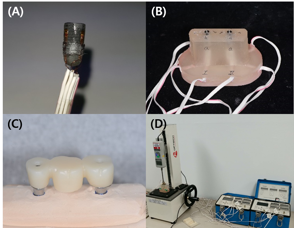
Fig. 1
Experimental setup and measurement procedures. (A) Implant fixture with strain gauges attached to the cervical area, (B) Acrylic resin experimental model with two implants, (C) Fabricated three-unit implant-supported fixed prosthesis, (D) Loading apparatus used during cementation and strain measurement.
Table 1.
Experimental specimens (torque unit = Ncm)
| N | 1st torque | Final torque | Material | |
| Co | 5 | 30 | Ni-Cr | |
| Me10 | 5 | 10 | 30 | Ni-Cr |
| Me30 | 5 | 30 | 30 | Ni-Cr |
| Go10 | 5 | 10 | 30 | Gold |
| Go30 | 5 | 30 | 30 | Gold |
| Zi10 | 5 | 10 | 30 | Zirconia |
| Zi30 | 5 | 30 | 30 | Zirconia |
Strain values were measured 10 min after load removal in Group Co using a strain gauge indicator (P3 Strain Indicator; Micro-Measurements, Raleigh, NC, USA). In the SCRP groups, the abutments and prostheses were removed to eliminate excess cement and reconnected with a final torque of 30 Ncm, and the strain values were recorded again after 10 min.
Five specimens were tested per group and eight strain values were obtained for each specimen. Absolute strain values were calculated to assess the overall stress magnitude. Data normality was confirmed using the Shapiro–Wilk test, and independent t-tests were performed for statistical analysis.
Ⅲ. Results
Absolute strain values were calculated for Group Co and all experimental groups, and the mean and standard deviation were determined (Fig. 2). The measured strain values are listed in Table 2.
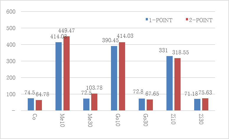
Table 2.
Mean strain values (mean ± standard deviation) of each experimental group (unit: μ ε)
No significant differences in strain values were observed between one- and two-point loading during cementation in any group (p > .05) (Table 3).
Table 3.
T-test between 1- and 2-point loading
| Group | P-value |
| Co | .714 |
| Me10 | .571 |
| Me30 | .137 |
| Go10 | .427 |
| Go30 | .800 |
| Zi10 | .835 |
| Zi30 | .800 |
Regardless of the loading method, significantly higher strain values were observed in Groups Me10, Go10, and Zi10 than in Groups Me30, Go30, and Zi30 and Group Co (p < .05). In contrast, no significant differences were found between Groups Me30, Go30, and Zi30 and the control group (Group Co) (p > .05).
When strain values were compared according to the prosthesis material, Group Me10 exhibited a significantly higher strain value than Group Zi10 under one-point loading (p < .05). However, no statistically significant differences were observed among the prosthesis materials in the other groups under either loading condition (Table 4).
Table 4.
P-values for all statistical comparisons (1-point/2-point)
| Me10 | Me30 | Go10 | Go30 | Zi10 | Zi30 | |
| Co | .000* / .000* | .937 / .098 | .000* / .000* | .953 / .866 | .000* / .002* | .899 / .553 |
| Me10 | .000* / .002* | .472 / .558 | .000* / .000* | .016* / .160 | .000* / .000* | |
| Me30 | .000* / .000* | .926 / .123 | .000* / .012* | .934 / .236 | ||
| Go10 | .000* / .000* | .091 / .130 | .000* / .000* | |||
| Go30 | .000* / .002* | .987 / .664 | ||||
| Zi10 | .000* / .003* |
Ⅳ. Discussion
Strain gauge analysis enables sensitive detection of deformation by measuring changes in electrical resistance under applied stress.17, 18, 19 Compared with photoelastic or finite element analysis, this method provides direct and reliable experimental data for quantifying small differences in stress magnitude.20, 21, 22, 23 Accordingly, strain gauge analysis was selected as the primary measurement method in this study.
Accurate strain measurements depend on both gauge location and fixation. While previous studies embedded strain gauges within resin models or attached them to resin surfaces,24, 25 the present study aimed to approximate peri-implant marginal bone conditions by applying a thin (0.5 mm) acrylic resin layer over the implant fixture surface and attaching strain gauges directly to this layer. An epoxy phenolic adhesive was used to ensure stable bonding suitable for precision measurements.26
During clinical cementation, patients are typically instructed to apply an occlusal force. The reported maximum bite forces range from approximately 430 to 596 N.27, 28, 29 Assuming that cementation forces are lower than the maximal bite force, the loading protocol in this study was designed to simulate clinically relevant conditions using sequential loading of 30 and 10 kg.
Strain values were recorded after abutment connection and cementation, with initial values zeroed to eliminate residual stress. Measurements were obtained after a stabilization period, consistent with previous studies.30 Absolute strain values were used to evaluate the overall stress magnitude irrespective of tensile or compressive direction, allowing consistent comparison among groups. However, this approach limits the interpretation of directional biomechanical behavior, and directional strain patterns are beyond the scope of this study and should be investigated in future research.
The results demonstrated that the initial stress around the implant fixtures remained low when the abutment tightening torque applied before cementation matched the final tightening torque in SCRP restorations using internal-connection implants. In contrast, significantly higher strain values were observed when the abutments were initially tightened at a lower torque and subsequently retightened to a higher final torque. Clinically, a reduced initial tightening torque is sometimes applied to facilitate prosthesis removal after cementation. However, the present findings suggest that such a torque mismatch should be avoided.
This increased stress may be explained by axial displacement at the internal implant–abutment interface. Previous studies have reported greater axial displacement in internal-connection implants with increasing torque.15 When the final tightening torque exceeds the initial torque, additional axial displacement may occur, potentially generating increased stress due to volumetric mismatch between the implant and abutment components. Reduced axial displacement has been reported in implants with larger diameters,31 suggesting that implant design may influence stress behavior during SCRP procedures.
Despite substantial differences in the elastic moduli of the prosthetic materials, no consistent material-related differences in stress generation were observed. This may be attributed to standardized prosthesis geometry, sufficient connector thickness, and rigid implant–abutment support under controlled experimental conditions. In clinical situations with limited prosthetic space or a compromised connector design, material properties may exert a greater influence and warrant further investigation.
Although perfect passive fit is rarely achieved clinically, stress should be maintained within a biologically acceptable range to preserve peri-implant bone homeostasis.17, 32, 33, 34 Wiskott and Belser have reported that bone can maintain homeostasis within a strain range of approximately 50–1,500 µε.34 The strain values observed in this study fall within this range, supporting the clinical relevance of minimizing stress during prosthesis installation.
From a clinical perspective, matching the abutment tightening torque before and after cementation is recommended when planning SCRP restorations using internal-connection implants. Alternatively, supragingival margin designs that permit cement removal without prosthesis detachment may help preserve retrievability, while minimizing stress generation.
Ⅴ. Conclusion
The findings of this study support the hypothesis that matching the abutment tightening torque before and after cementation is critical for minimizing the initial stress around the implant fixtures in screw-cement-retained prostheses using internal-connection implants. When the initial and final tightening torque values were consistent, the stress generated around the implant fixture was comparable with that of conventional cement-retained restorations. By contrast, a mismatch between the initial and final tightening torques resulted in increased stress. Prosthesis material did not significantly influence the initial stress generation under the standardized experimental conditions used in this study. Clinically, careful control of the abutment tightening torque during SCRP procedures may help reduce unintended stress and contribute to long-term implant stability.
