

Ⅰ. Introduction
Complete mouth rehabilitation, including various aspects such as centric relation (CR), vertical dimension of occlusion, diagnostic wax-up, and setting prostheses, is challenging and demanding for dentists.1,2 Traditionally, laboratory procedures using prostheses were performed on mechanical articulators.3,4 In the conventional method, replicating previous prostheses throughout the entire treatment process proved difficult.5 Moreover, mechanical articulators have a fixed intercondylar distance and limited capabilities to reproduce dynamic occlusion, leading to errors during mounting procedures.3,6,7
Advancements in digital dentistry have made it possible to easily adjust prosthetic designs and replicate previous prostheses using virtual articulators.8,9By integrating jaw motion analysis records, virtual articulators can be fully adjustable.7,10 Additionally, creating a virtual patient allows for more accurate treatment predictions by matching multi-source digital data including intraoral scans, facial scans, and jaw motion analysis records.5,8,10,11 Recently, a technique was published that involved creating a virtual patient and predicting occlusal relationships through jaw motion analysis.8,10,12 This approach enables designing prostheses that are parallel to the interpupillary line and aligned with dental and facial midlines, whilst static and dynamic occlusions are also considered. This clinical report describes a digital treatment workflow for complete mouth rehabilitation, through the creation of a virtual patient with dynamic occlusion.
Ⅱ. Case report
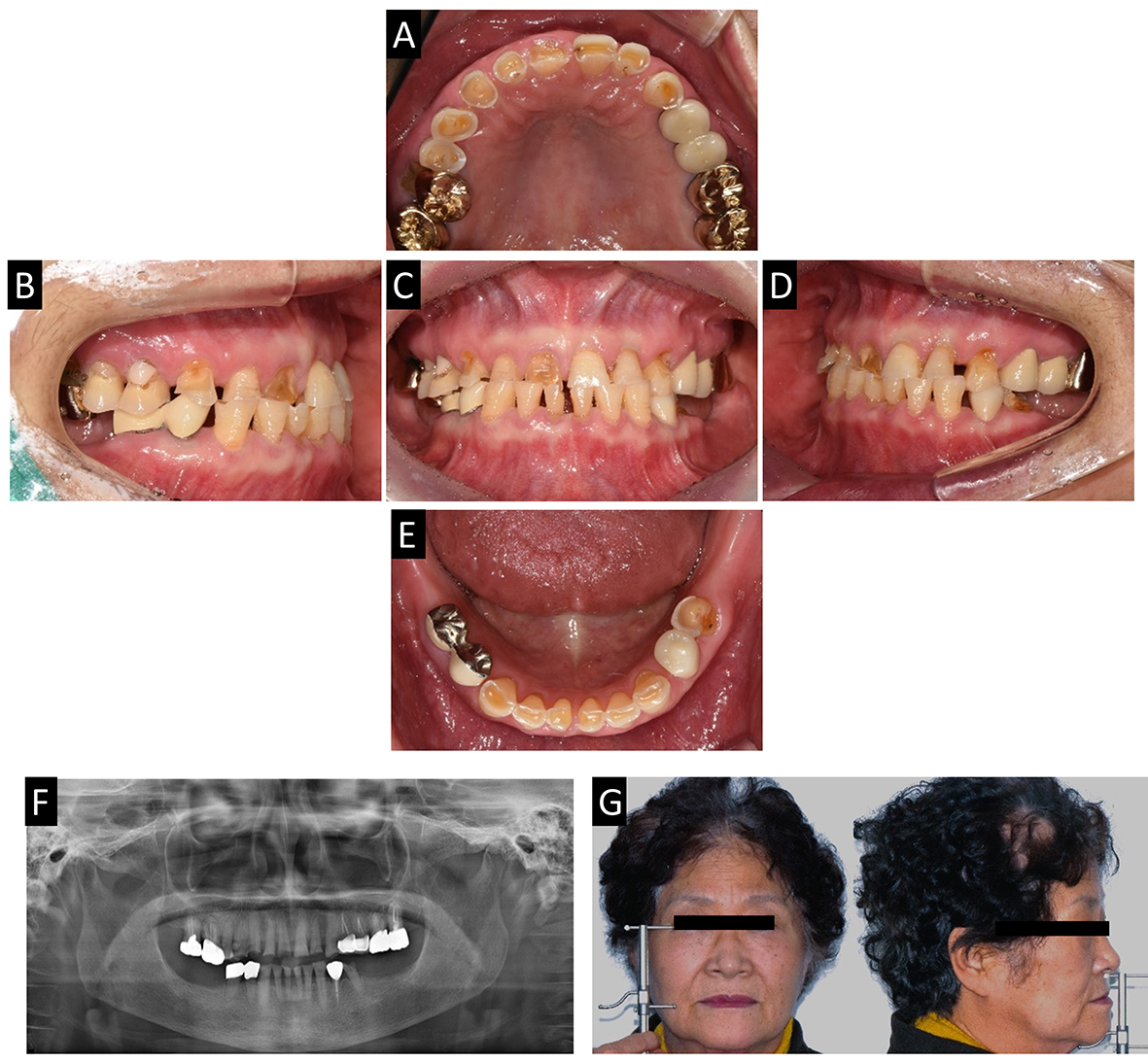
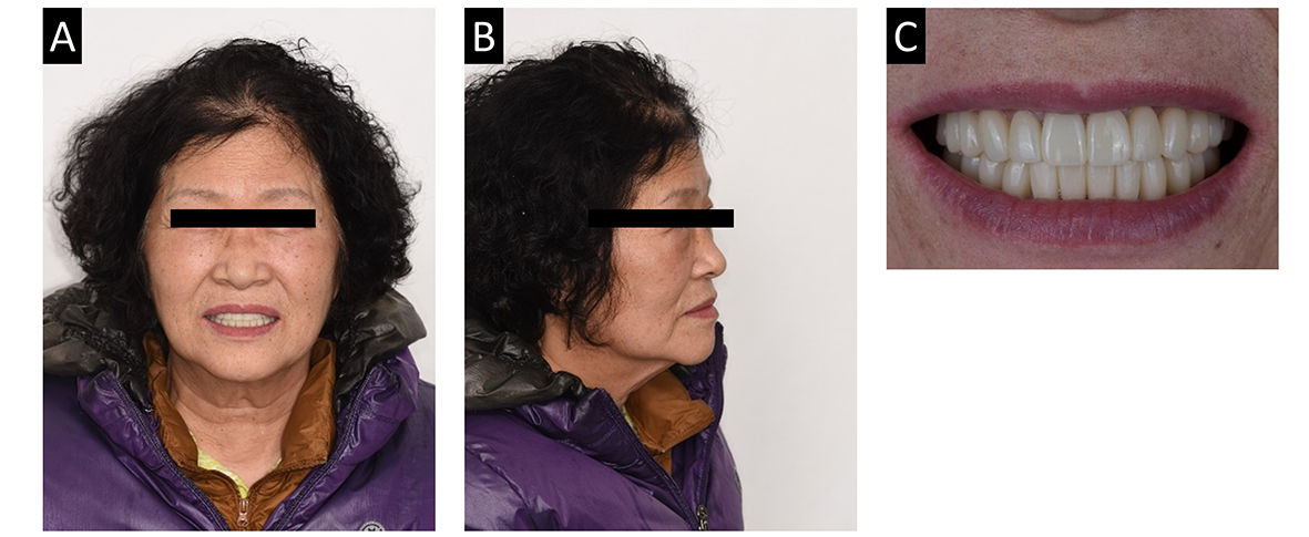
A 72-year-old female patient presented with generalized wear on the occlusal surface. Her chief complaint was, “My teeth are worn out and I can't chew well. I’d like to receive comprehensive treatments.” (Fig. 1). The patient had no systemic disease. Generalized wear due to bruxism was observed, as well as decreased vertical dimension of occlusion. Extrusion of posterior maxillary teeth and no restoration of posterior mandibular teeth resulted in irregular occlusal plane. Furthermore, wear on the anterior teeth caused an edge-to-edge bite.
As part of optimal planning, implants on both mandibular posteriors were strategically planned. The goal of treatment was to achieve immediate improvement in the occlusion by providing maximum intercuspal contact at centric relation and establishing a mutually protected occlusion during eccentric movements.
The centric relation was recorded by increasing the vertical dimension by 4 mm using a Lucia jig and performing diagnostic wax-up after mounting on a semi-adjustable articulator (Artex CR, Amann Girrbach, Koblach, Austria) (Fig. 2). The freeway space was 6 mm, the difference between the length of the upper and lower face was 6 mm when analyzed using the Willis method, and the canine-to-canine length was 3 mm shorter than the average for Korean women; hence, 4 mm elevation was performed. The diagnostic wax-up was fabricated using the Calotte device, and the diagnostic wax-up and jaw relation were scanned on the CAD program. The occlusal plane was checked using the Calotte device (Fig. 2C). Provisional prostheses were fabricated using the diagnostic wax-up. The provisional crown jigs were also created for minimal occlusal adjustment on a computer-aided design (CAD) software program (Ceramill mind, Amann Girrbach) considering complete mouth rehabilitation. This was done by integrating the wax-up scan file and first diagnostic casts. The first provisional prosthesis was evaluated in terms of pronunciation, aesthetics, occlusion, and temporomandibular joint after an adaptation period of 2 months (Fig. 3).

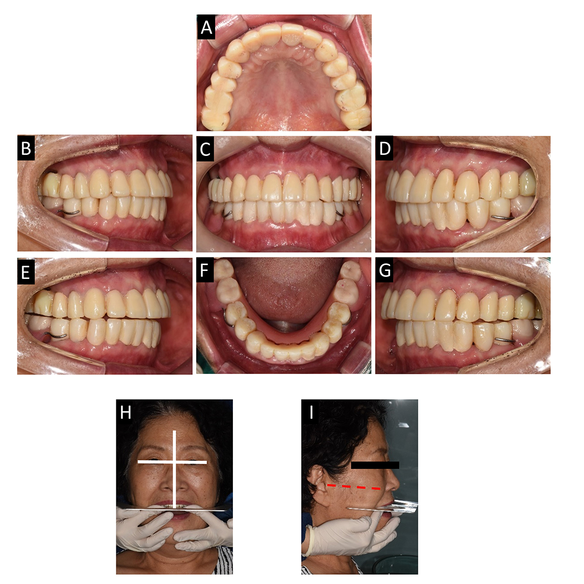
Fig. 3.
Delivery of 1st provisional prosthesis and analysis with the face. (A) Maxillary occlusal view, (B) Lateral view (right), (C) Frontal view, (D) Lateral view (left), (E) Canine guidance at right side, (F) Mandibular occlusal view, (G) Canine guidance at left side, (H) Checking for parallelism with the horizontal line of the maxillary anterior teeth and interpupillary line, (I) Checking for parallelism with the horizontal line of the maxillary mandibular teeth and Camper’s line.
To establish the location of the implants, a radiographic stent was constructed with a replica of the provisional removable partial denture, and a cone beam computed tomography (CBCT) scan was taken after the stent was delivered. A digital guide was created by matching the intraoral scan data and CBCT data, and the implants were planned on a CAD program (3shape Implant Studio, 3shape, Copenhagen, Denmark) (Fig. 4). Implant fixtures (Osstem TS III, Osstem, Seoul, Korea) were placed using implant guides on the tooth #36,37,46 and 47 partial edentulous areas. After a 3-month osseointegration period, a digital impression was taken using scan bodies and an intraoral scanner (Trios 3, 3shape). The implants were restored with customized abutments and provisional prosthesis.

For the second provisional prosthesis, the three-dimensional position of the maxilla and mandible was digitally cross-mounted in the CAD program (Ceramill mind, Amann Girrbach), and a virtual patient was created using facial scan data. Both the smile line and midline of the virtual patient were incorporated into the anterior teeth designs. A jaw motion analyzer (Zebris for Ceramill, Amann Girrbach) was used to design the second provisional prosthesis according to a mutually protected occlusion (Figs. 5 and 6). Factors such as pronunciation, aesthetics, occlusion, and anterior guidance were meticulously inspected. The second provisional prosthesis was restored (Fig. 7).

Fig. 5.
Digital facebow (Zebris for ceramill) procedure and virtual articulator. (A) Bite fork and Bite fork adapter, (B) Scan data of maxillary bite fork, (C) Determining upper jaw position with bite fork, (D) Determining reference plane with a T-pointer, (E) Mandibular movement device, (F) Virtual mounting on virtual articulator, (G) Measurement of mandibular movements for the setting of the virtual articulator.

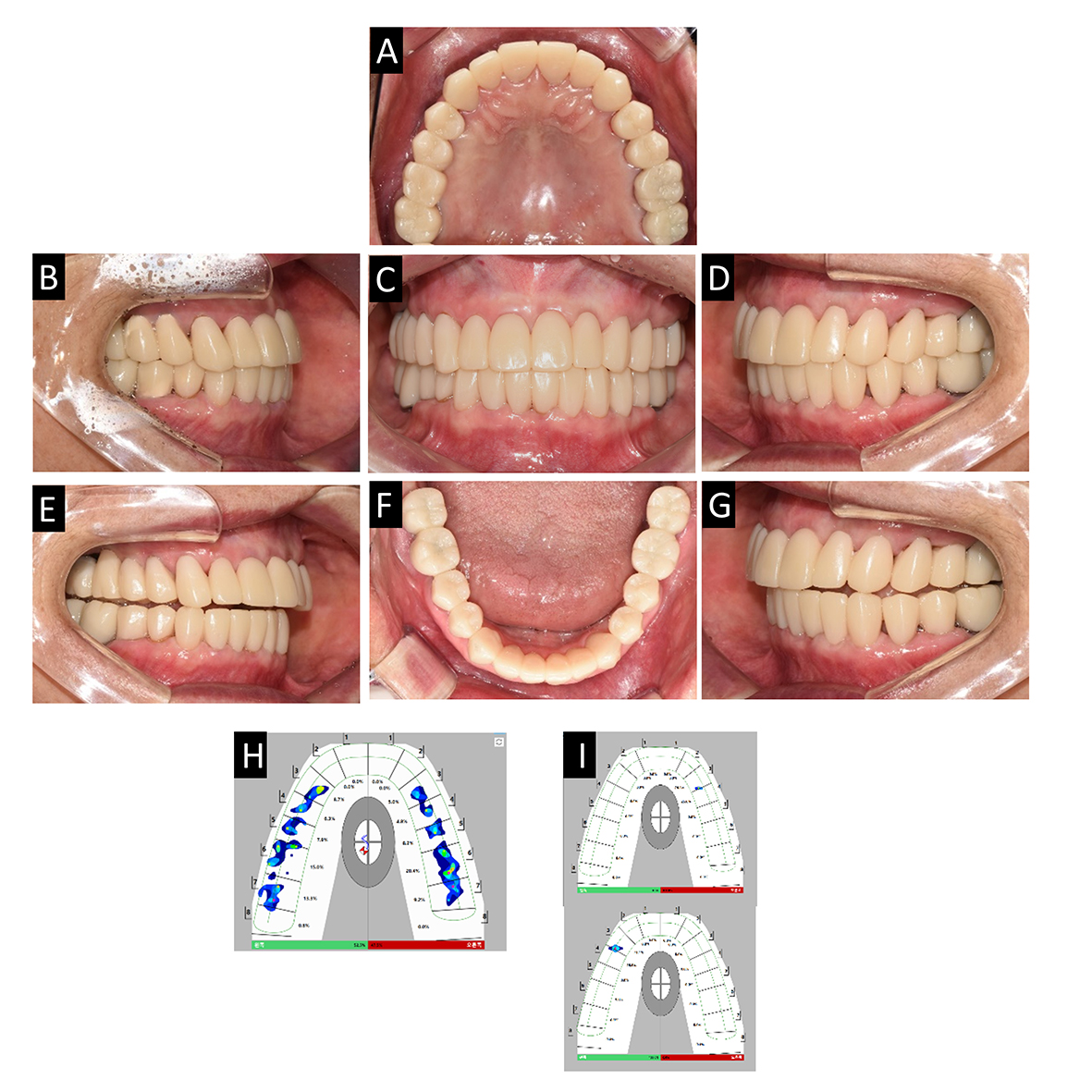
Fig. 7.
Delivery of 2nd provisional prosthesis. (A) Maxillary occlusal view, (B) Lateral view (right), (C) Frontal view, (E) Lateral view (left), (E) Canine guidance at right side, (F) Mandibular occlusal view, (G) Canine guidance at left side, (H) T-scan result of maximal intercuspal position, (I) T-scan results of right and left canine guidance.
The definitive prosthesis was divided into anterior and posterior parts. It was designed using a double-scanning technique,13(Fig. 8) by overlapping the digital scan data of the second provisional prosthesis and the anterior guidance data from jaw motion analyzing data. After mounting the master casts on the semi-adjustable articulator, the anterior guidance was verified without interference by compensating for the limitations of manufacturing without a master cast. Finally, functional adjustments were performed, and the pronunciation, aesthetics, occlusion, and protrusive movement were evaluated in the patients. A T-scan was performed to determine that the final prosthetic restoration achieved harmonious occlusion with mandibular movement through immediate disocclusion on posterior portions as induced by the mutually protected occlusion (Fig. 9).

Fig. 8.
Fabricating definitive prosthesis. (A) Anterior teeth preparation, (B) Double scan for anterior final prosthesis, (C) Articulator mounting for checking guidance, (D) Posterior teeth preparation, (E) Double scan for posterior final prosthesis, (F) Articulator mounting for checking guidance, (G) Calculated articulator setting parameters in Zebris for ceramill.
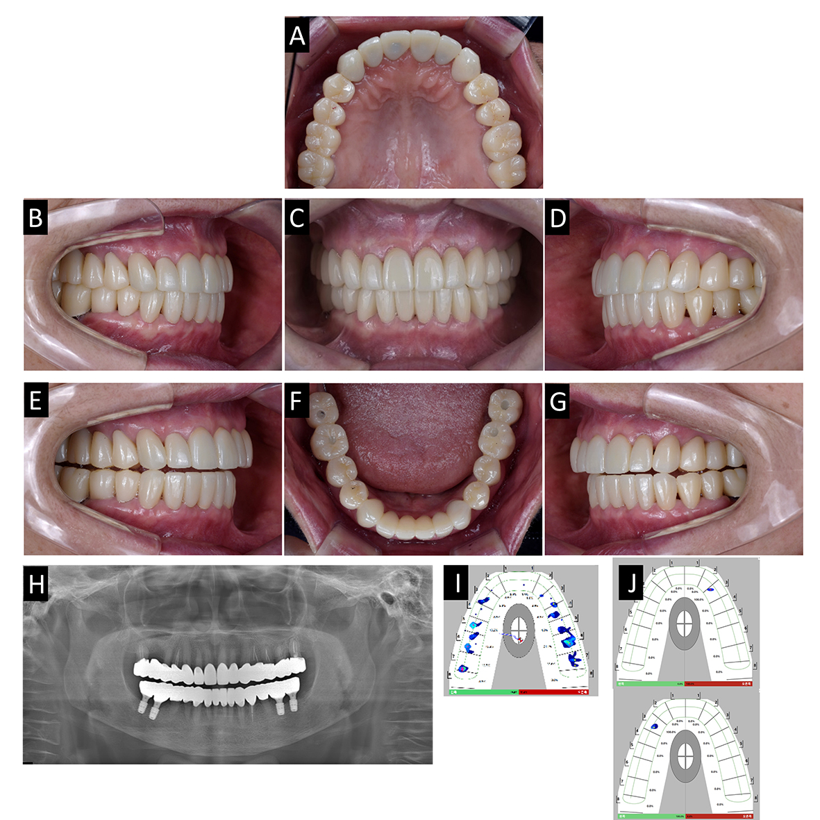
Fig. 9.
Delivery of definitive prosthesis. (A) Maxillary occlusal view, (B) Lateral view(right), (C) Frontal view, (E) Lateral view (left), (E) Canine guidance at right side, (F) Mandibular occlusal view, (G) Canine guidance at left side, (H) Panoramic radiograph, (I) T-scan result of maximal intercuspal position, (J) T-scan results of right and left canine guidance.
Ⅲ. Discussion
In this clinical report, a virtual patient was created through a three-step integration process: smile state, resting state, and facial scan jig scan.13 After creating the virtual patient, the accuracy of the integration was verified by confirming the alignment of the midline in the oral scan data with the face and ensuring parallelism between the anterior incisal edge and interpupillary line (Fig. 3).8 The design of the anterior smile took into consideration factors such as ideal crown shape, overjet, and overbite, while the occlusal plane was properly determined (Fig. 10).14 This allowed the dentist to visually communicate the prosthetic design with the patient.
In this report, the patient’s case involved the elevation of the vertical dimension. Therefore, the primary indication for using a completely adjustable type of virtual articulator was, in this complex case, the occlusal plane needing to be assessed in static and dynamic occlusion to avoid interferences. Various direct digital impressions were used for digital cross-mounting, enabling the alignment of the three-dimensional positional relationship between the upper and lower jaws in a CAD program. Virtual contacts observed are more accurate than those obtained conventionally, resulting in a shorter time requirement for occlusal adjustment and laboratory procedure.15
Ⅳ. Conclusion
Complete mouth rehabilitation was performed on a patient who experienced severe wear of the occlusal surface and shortened vertical dimension. The fabrication of the prostheses involved creating a virtual patient and using a jaw motion tracker, as well as employing the computer aided design and computer aided manufacturing(CAD-CAM) double-scanning technique to enhance the predictability of the treatment. This technique can produce definitive prostheses as easily as duplicating provisional prostheses and improving the predictability of the treatment.
