

Ⅰ. Introduction
Restoration using removable partial denture due to mandibular posterior tooth loss until the implant procedure is established has been applied over the years. Particularly, since vertical bone loss occurs in patients with removable partial dentures due to the loss of a mandibular posterior tooth, it is often difficult to place an implant at an appropriate position, where the tooth was positioned initially.
In the clinical cases, vertical bone augmentation was required to place an implant at an appropriate position, and autogenous block bone graft, which is advantageous for vertical maintenance of the shape with excellent osteogenesis, was preferentially considered.1 Autogenous alveolar bone augmentation shows good results for alveolar bone with severe vertical and lateral bone defects.2 If a block-shaped autogenous bone is used as a technique to restore the part with vertical and lateral bone defects, it is advantageous for maintaining the shape since there is less absorption after implantation because of its hard bony tissue, and predictable osteogenesis can be expected.3 In addition, in various regions such as regions with vertical and lateral bone deficiencies where no membrane barrier can be used due to severe bone defects and the regions where vertical bone augmentation and alveolar bone ridge augmentation are conducted, an implant can be placed through a block-shaped autogenous bone graft, which is more advantageous for initial fixation in implant surgery because of the hard cortical bone.4
First, an osseointegrated implant was discussed by Brånemark et al. who used the iliac crest as a donor site for alveolar bone implantation.5 However, if the iliac bone is used for autogenous alveolar bone augmentation for the implant, general anesthesia is needed, and the surgical site will extend to the iliac bone as well as the oral cavity, thus leading to many inconveniences after surgery. At this time, if as intraoral autogenous bone, the mandible is used, an excellent primary cortical bone can be obtained in lateral and vertical bone augmentation, which has many advantages, including the proximity between the donor site and recipient site, traditional surgical approach, and lower cost. For intraoral vertical bone augmentation, the original bone density can be maintained using intraoral cortical bone. This is because harvesting is easy, and absorption can be minimized.
Moreover, these grafts are well combined with the bone in the recipient site in a predictable way. Moreover, these processes can be efficiently and conveniently implemented in the outpatient department of the dental clinic.
In harvesting block bone in the mandible, if the implant surgery region is the posterior teeth region, the mandible is harvested after a block in the mandibular ramus posterior to implant surgery or the retromolar region, and if a bone graft is performed, no additional surgical site is created, so the surgical time and healing period are shorter.
In harvesting intraoral autogenous block bone, the harvesting apparatus is also important. If the block bone is harvested using a low-speed straight handpiece and fissure bur often used to perform corticotomy, damage may occur on the lips and soft tissues by the shank of the fissure bur, and the cut cortical bone may not be clean. However, it is possible to harvest the autogenous block bone safely and cleanly using a piezoelectric device.
Thus, the author obtained good results by performing delayed implant surgery after implementing vertical bone augmentation, harvesting autogenous block bone without creating any additional surgical site for the donor site. This was achieved by harvesting the block bone safely from the region posterior to the surgical site in patients who needed vertical bone augmentation due to the vertical and lateral bone defects that occurred vertically to the posterior tooth.
Ⅱ. Case Report
1. Case 1
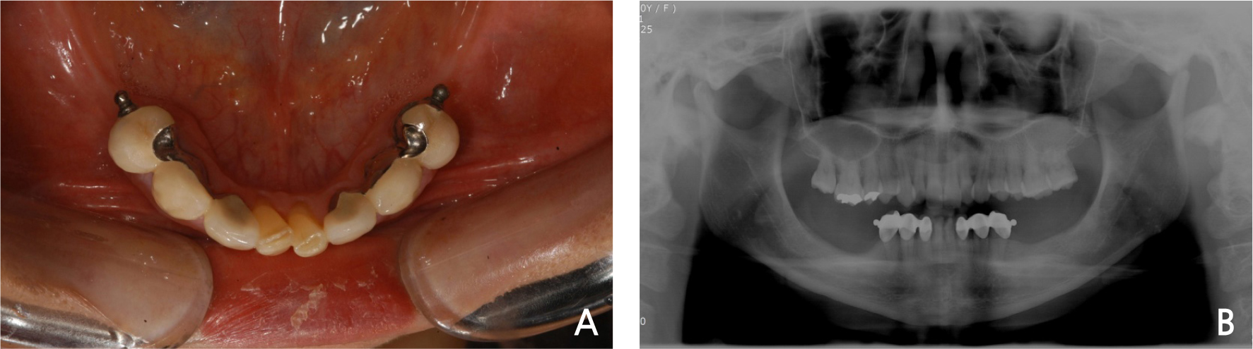
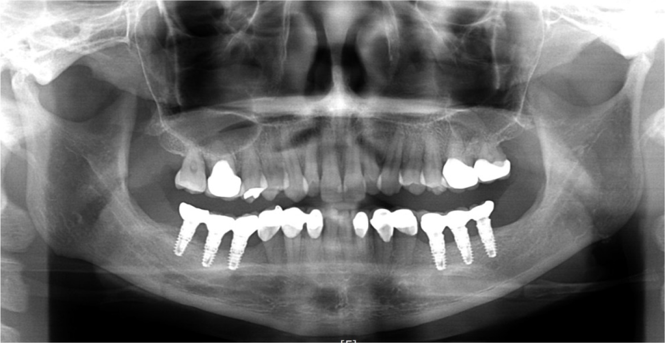
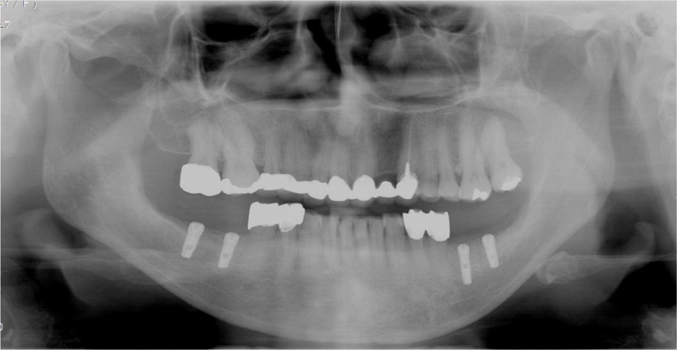
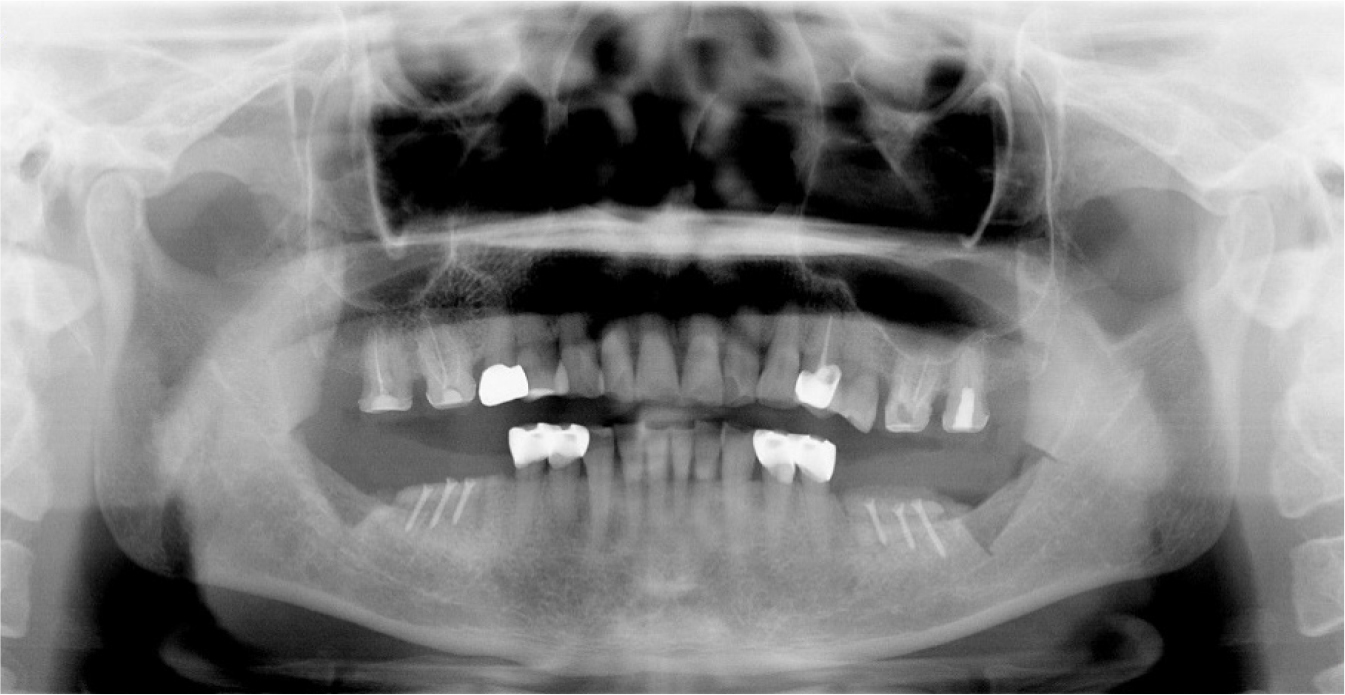
A 30-year-old female patient was referred to the hospital from a local dental clinic for posterior tooth block bone graft and implant surgery. The patient had a removable partial denture in place due to the loss of posterior teeth (Fig. 1A). She desired to have fixed prosthetics using implants instead of removable partial dentures. On panoramic photography, a 3–4-mm vertical bone loss was observed in about at the mandibular posterior areas on both sides due to the long fitting of the removable partial denture. Thus, implant surgery was planned after 3–4-mm vertical bone augmentation by the implementation of a block bone graft (Fig. 1B).
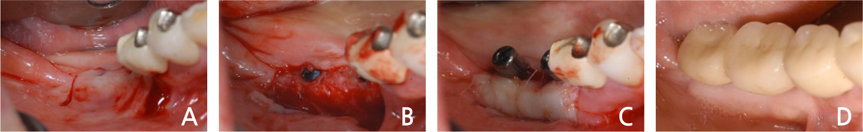
For the donor site of the autogenous block bone used at this time, harvesting was planned at the mandibular ramus and retromolar area of the posterior tooth requiring bone augmentation. First, surgery was planned to start in the right mandibular region. An incision was made on the right mandibular surgical site after local anesthesia (2% lidocaine with 1:100,000 epinephrine, Yuhan, Korea) (Fig. 2A). After the periodontal flap was elevated, it was marked with a pencil to harvest the mandibular autogenous block bone posteriorly to the surgical recipient site (Fig. 2B), and then, using a piezoelectric device (Piezosurgery Ⓡ , Mectron, Italy), the cortical bone was cut in the mandibular ramus and retromolar area (Fig. 2C, 2D). After the corticotomy, block bone measuring 2–2.5-cm wide, 1-cm long, and 5-mm thick was harvested (Fig. 2E). In order to reduce hemorrhage at the mandibular donor site (Fig. 2F), a hemostatic agent (Surgicel Ⓡ , Ethicon, USA) (Fig. 2G) was used to arrest the bleeding (Fig. 2H). Then, a hole was bored at the recipient site and the preparation was performed (Fig. 2I). The harvested block bone was fixed using a micro screw to conduct a vertical block bone graft (Fig. 2J). Additionally, a particulate allogeneic bone (Puros Ⓡ , Zimmer Biomet, USA) graft was operated (Fig. 2K) and sutured with a continuous locking suture without tension (Fig. 2L).
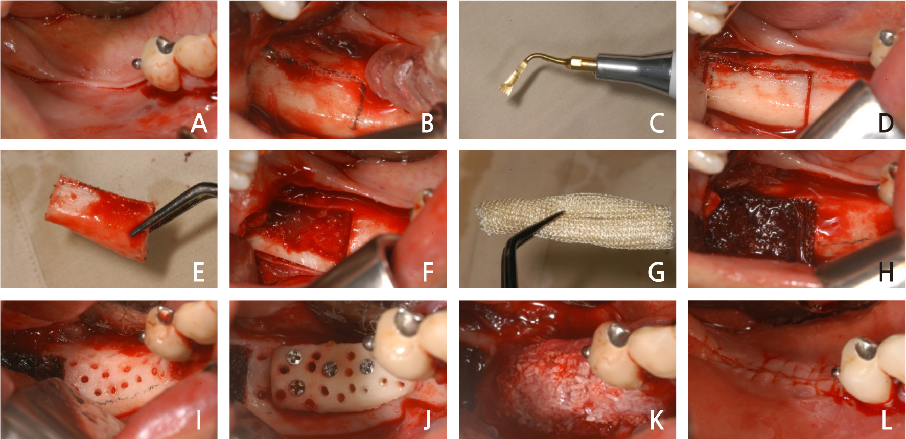
Fig. 2.
Case I: Intraoral views of autogenous ramal block bone graft surgery (right). (A) Incision. (B) Fullthickness flap was elevated. (C) Piezoelectric device (Piezosurgery Ⓡ ). (D) Corticotomy at the donor site. (E) Harvest of autogenous block bone. (F) Donor site. (G) Hemostatic agent (Surgicel Ⓡ ). (H) Donor site with a hemostatic agent (Surgicel Ⓡ ). (I) Recipient site preparation. (J) Fixation with microscrews. (K) Addition of particulate allograft. (L) The flap was sutured.
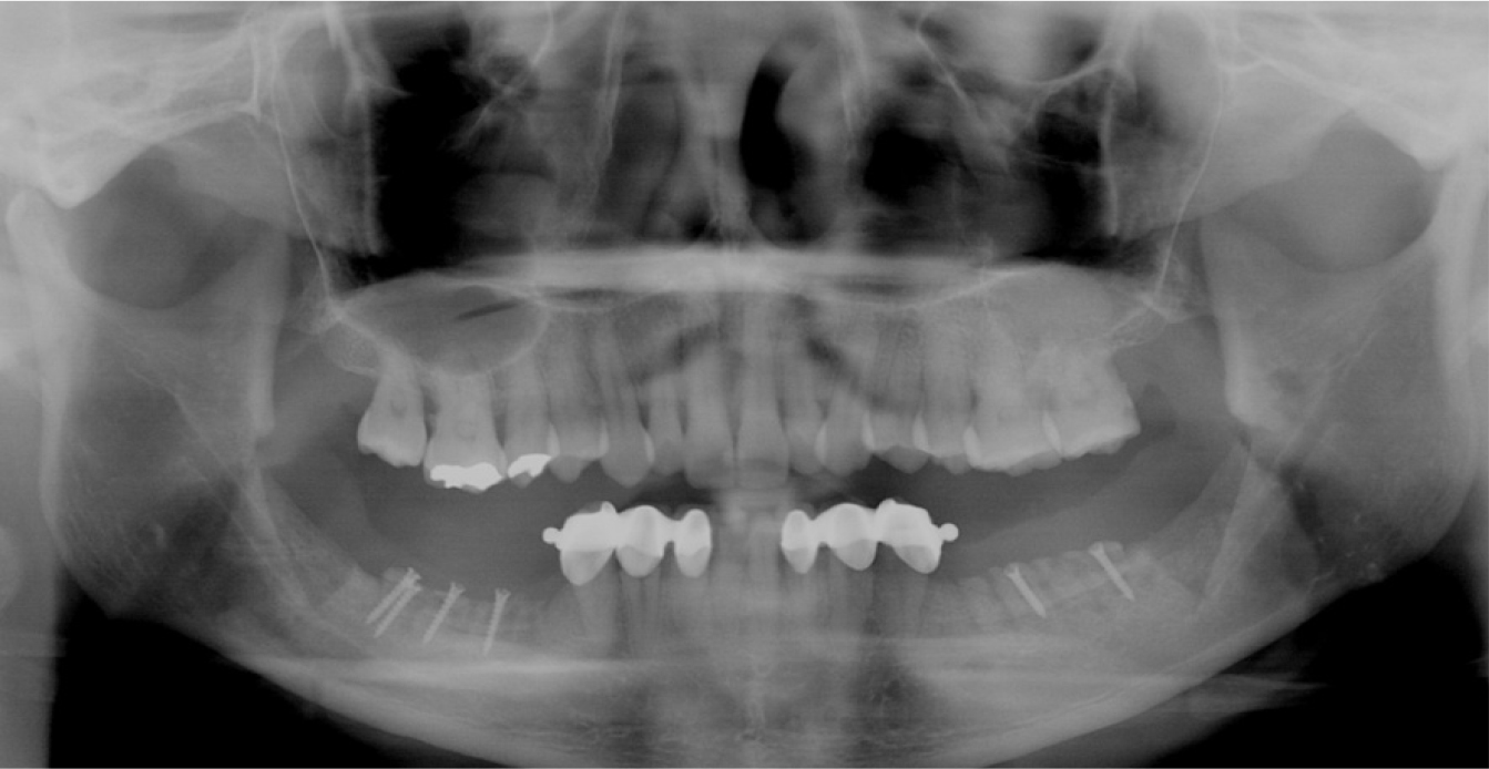
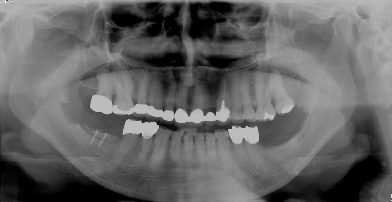
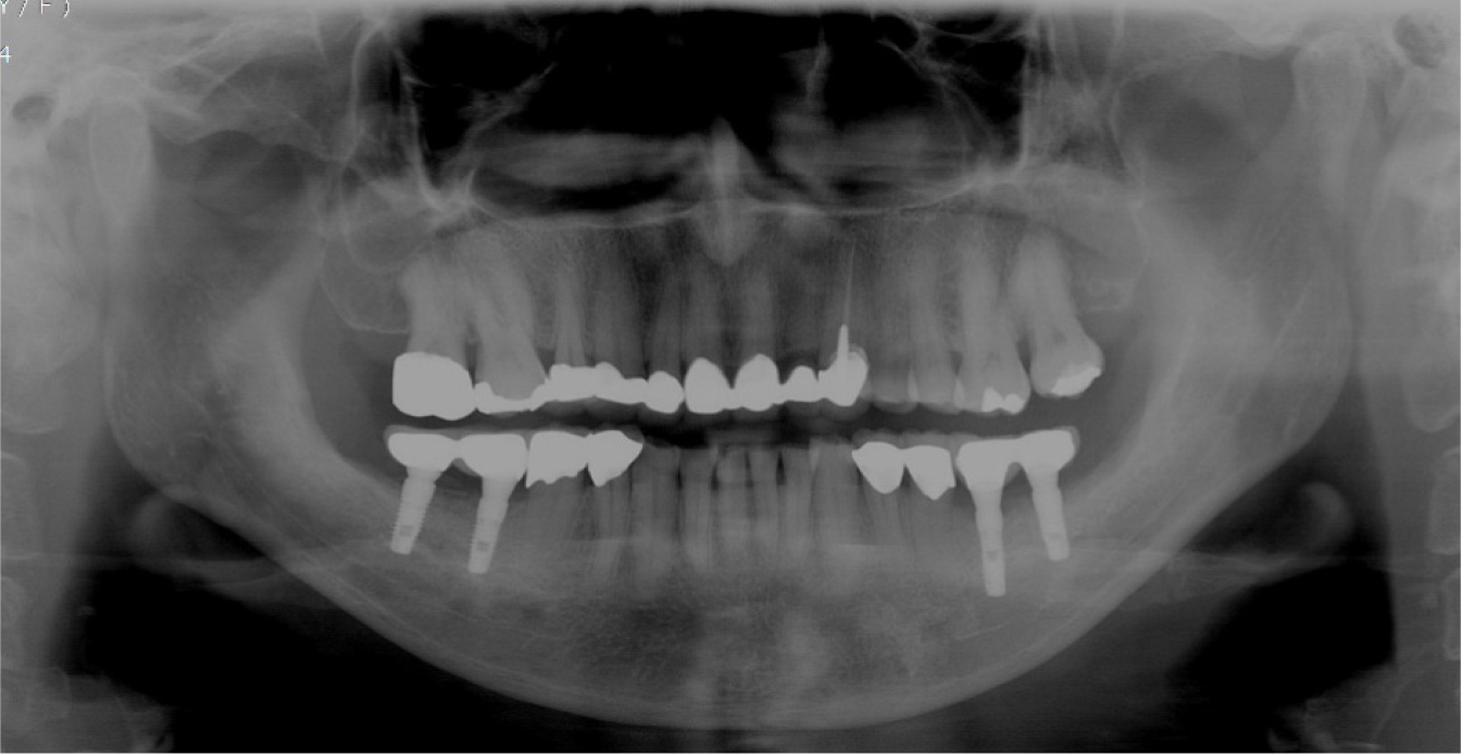
One month after the right mandibular molar block bone graft, a left molar block bone graft was performed. Similar to the right side, an incision was made after local anesthesia at the surgical site (Fig. 3A). After the surgical site flap was elevated (Fig. 3B), an autogenous bone from the mandibular left ramus, and the retromolar area were harvested. Corticotomy was then performed using a piezoelectric device (Fig. 3C). For the corticotomy of the lower region of the cortical bone, autogenous block bone measuring 2-cm wide, 1.5-cm long, and 4-mm thick was cleanly cut using a disc wheel (MicroSaw Ⓡ , Dentsply, USA) (Fig. 3D) to harvest it (Fig. 3E, 3F). For hemostasis of the donor site, hemorrhage was arrested using a hemostatic agent (Fig. 3G, 3H). A hole was formed on the harvested autogenous block bone for better blood supply, and it was fixed on the mandibular left molar using a microscrew (Fig. 3I). After a particulate allograft was additionally used (Fig. 3J), it was sutured by a continuous locking suture (Fig. 3K). On postoperative panoramic views, the mandibular ramal block bone was harvested posteriorly to the surgical site. It was then observed that a vertical block bone graft was successful in the region of the mandibular molar anterior to the donor site with vertical and lateral bone defects (Fig. 4).
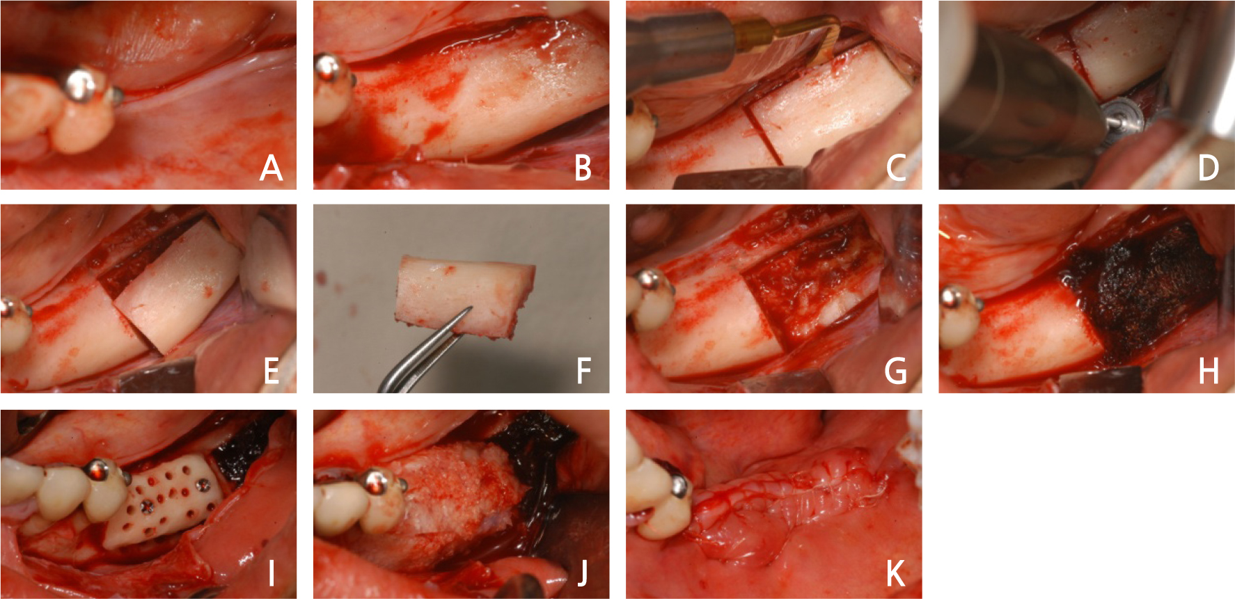
Fig. 3.
Case I: Intraoral views of autogenous ramal block bone graft surgery (left). (A) Incision of surgical. (B) Full-thickness flap was elevated. (C) Corticotomy at the donor site. (D) Corticotomy of the lower part with a disc wheel. (E), (F) Harvest of autogenous block bone. (G) Donor site. (H) Donor site with a hemostatic agent (Surgicel Ⓡ ). (I) Fixation with microscrews. (J) Addition of particulate allograft. (K) The flap was sutured.
Seven months after the right mandibular block bone graft, the first implant surgery was performed. After local anesthesia, a periodontal flap was elevated, and the grafted autogenous bone block was observed (Fig. 5A). On the surgical site, an 8-mm implant (Xive Ⓡ , Dentsply, USA) was placed. Additionally, an allogeneic bone was transplanted (Fig. 5B). An absorbable membrane (Lyoplant Ⓡ , B. Braun, Germany) was used in the allogeneic bone graft (Fig. 5C) and sutured without tension (Fig. 5D). The first mandibular left implant surgery was performed 7 months after the block bone graft. The region where the block bone graft was performed healed adequately without any problems (Fig. 5E). An incision was made after local anesthesia, and a periodontal flap was elevated (Fig. 5F). At the block bone graft region, Xive Ⓡ 8-mm implants were placed (Fig. 5G), and the flaps were sutured well (Fig. 5H). On the postoperative panoramic view, it was observed that the implants were placed well at the right position (Fig. 6).
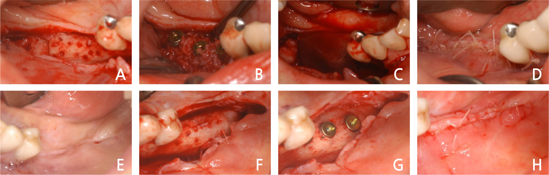
Fig. 5.
Case I: Intraoral views of the first implant surgery (both). (A) A full-thickness flap was elevated. (B) Implants were inserted with granules of allograft. (C) Absorbable membrane used. (D) The flap was sutured without tension. (E) Gingival condition before the first left surgery. (F) Full-thickness flap was elevated. (G) Implants were inserted. (H) The flap was sutured without tension.
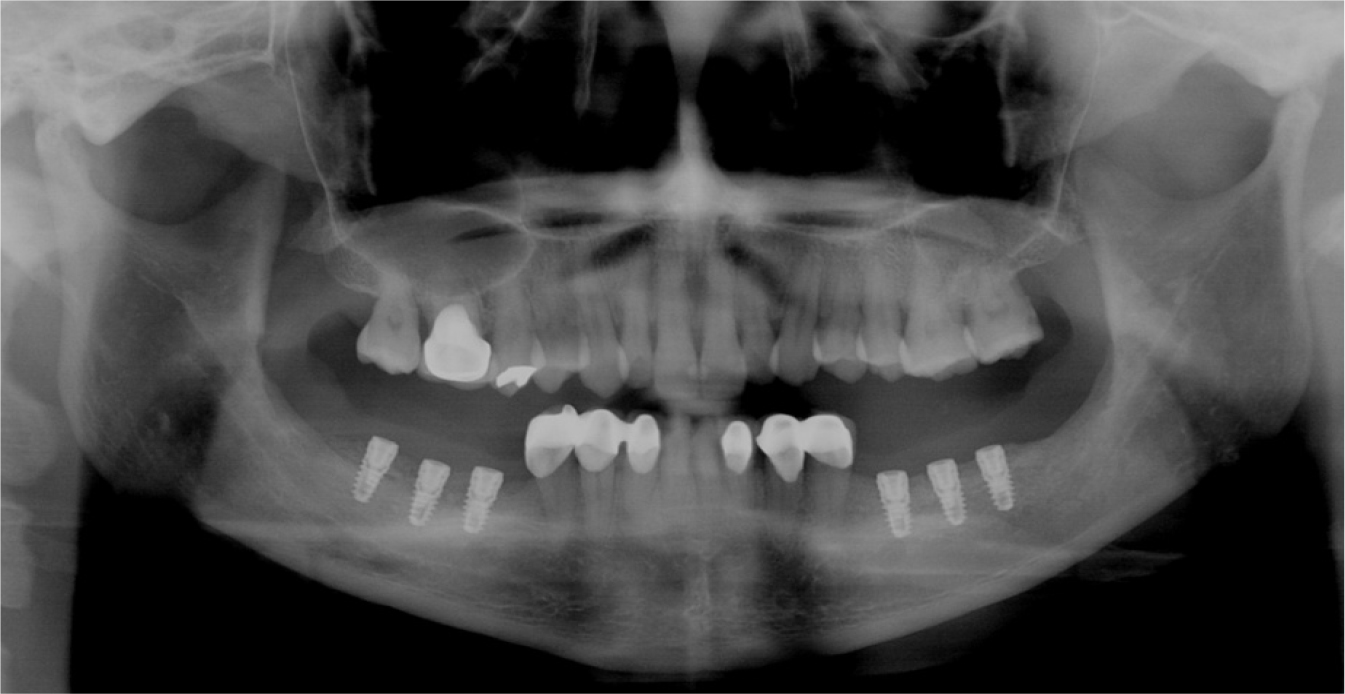
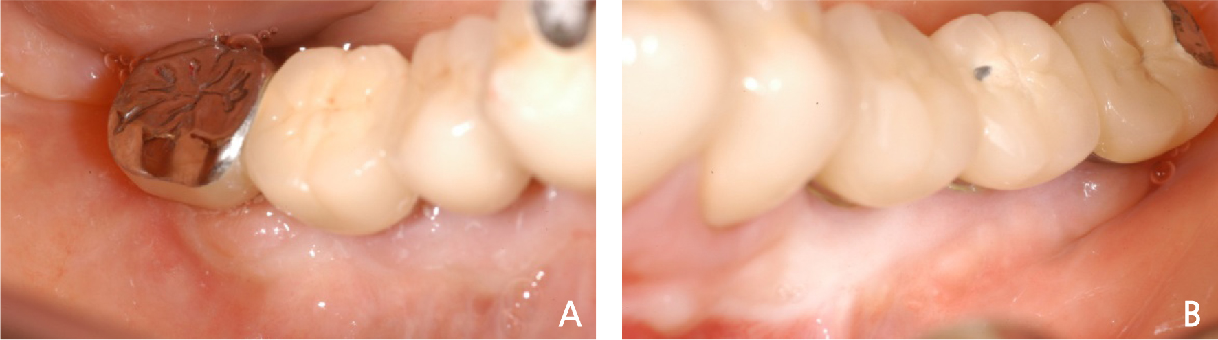
Six months after the first right mandibular implant surgery, a second surgery was performed. The surgical site was well healed, but the attached gingiva was lacking, so a free gingival graft (FGG) was planned (Fig. 7A). After local anesthesia, a partial-thickness flap was formed, and then an apically positioned flap was formed (Fig. 7B). After the cover screw was removed, the healing abutment was connected (Fig. 7C), and the gingiva harvested on the palate was sutured on the region where the partial-thickness flap was formed and fixed well for FGG placement (Fig. 7D). The second mandibular left surgery was performed 5 months after the implant surgery, and the attached gingiva looked very insufficient, so FGG placement was planned (Fig. 7E). As in the right site, a partial-thickness flap was formed (Fig. 7F), and then the cover screw was removed to connect the healing abutment (Fig. 7G). The palatal gingiva was transplanted in the region where the partial-thickness flap was formed to grow the attached gingiva by FGG placement (Fig. 7H). After the second surgery, the gingiva was well healed, the attached gingiva formed well, and the final restoration was installed in the posterior tooth (Fig. 8A, 8B). On the panoramic view, implant surgery was successful, and the final restoration was well installed (Fig. 9).
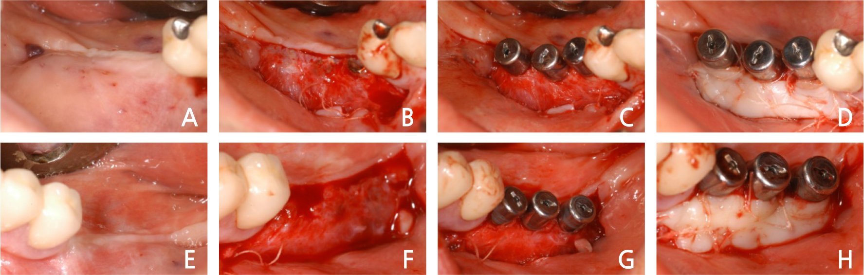
Fig. 7.
Case I: Intraoral views of the second implant surgery (both). (A) Gingival condition before the second right surgery. (B) Partial-thickness flap was elevated. (C) Healing abutments were placed on the implant. (D) Free gingival graft used. (E) Gingival condition before the second left surgery. (F) Partialthickness flap was elevated. (G) Healing abutments were placed on the implant. (H) Free gingival graft used.
2. Case 2
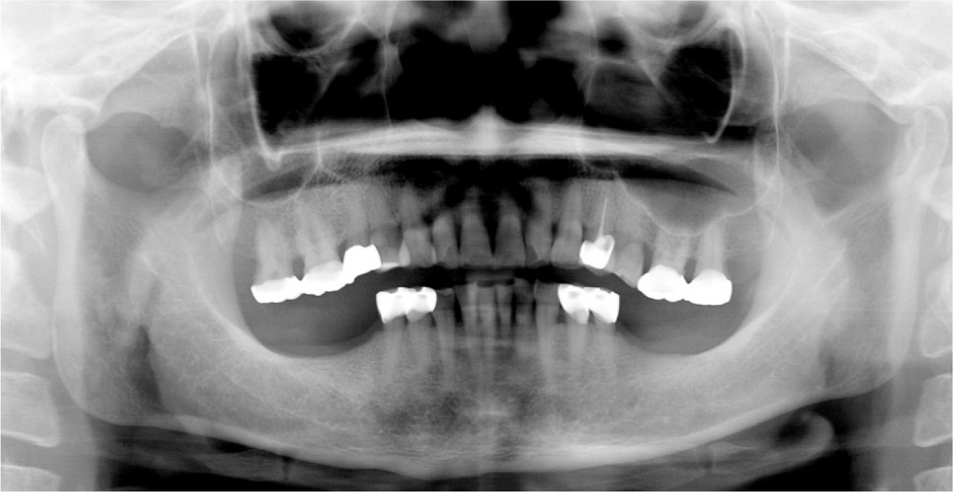
A 60-year-old female patient visited the hospital for consultation regarding a mandibular molar implant. Similar to the patient in Case 1, the patient had a removable partial denture in place due to loss of the mandibular molar on both sides, and thus, there was vertical alveolar bone loss. On the panoramic view, a 3–4-mm vertical bone loss on the right mandibular molar was observed, and a 5–6-mm alveolar bone up to the inferior alveolar nerve was left. Thus, for implant surgery, a 10-mm implant placement was planned after vertical ridge augmentation using the block bone graft (Fig. 10).
First, an incision was made on the surgical site at the right side of the mandible after local anesthesia (Fig. 11A). A full-thickness flap was formed, and the periodontal flap was elevated (Fig. 11B). The cortical bone was cut using a fissure bur (Fig. 11C) to harvest the block bone (Fig. 11D). To reduce hemorrhage at the donor site, a hemostatic agent was used (Fig. 11E), and ridge augmentation was performed vertically by fixing a block bone measuring 1.5-cm wide, 1-cm high, and 4-mm thick on the recipient site, using a microscrew (Fig. 11F). In addition, a particulate allograft was performed (Fig. 11G), and the surgical site was sutured without tension (Fig. 11H). On the postoperative panoramic view, 3–4-mm vertical ridge augmentation using the block bone was operated (Fig. 12). Five months after the block bone graft, the surgical site healed normally (Fig. 13A); thus, the flap was elevated for the first implant surgery (Fig. 13B). The block bone graft was good. For implant placement, drilling was performed. The path was set using a guide pin (Fig. 13C), and then a 10-mm-long implant (Implantium Ⓡ , Dentium, Korea) was placed (Fig. 13D). The panoramic view showed that the implants were well placed (Fig. 14). Four months after implant placement, incisions were made for the second implant surgery (Fig. 15A), and after elevation of the partial thickness flap (Fig. 15B), healing abutments were inserted, and FGG was performed simultaneously (Fig. 15C). A month and a half after the second implant surgery, implant prostheses were installed (Fig. 15D), and on the panoramic view, the prostheses were placed well (Fig. 16).
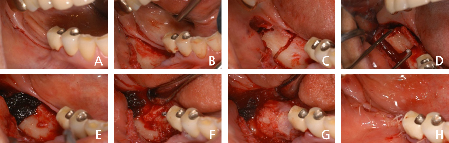
Fig. 11.
Case II: Intraoral views of autogenous ramal block bone graft surgery. (A) Incision of the surgical area. (B) Full-thickness flap was elevated. (C) Corticotomy of donor site. (D) Harvest of autogenous block bone. (E) Donor site with a hemostatic agent. (F) Fixation of block bone. (G) Addition of particulate allograft. (H) The flap was sutured.

3. Case 3
A 51-year-old female patient was referred from a local dental clinic to the hospital with a request for vertical ridge augmentation through block bone grafts on both sides of the mandible. On the panoramic view, there were 4–5-mm vertical bone losses on the mandible on both sides, and bone augmentation was planned through a block bone graft for implant surgery (Fig. 17).
First, an incision was made on the surgical site on the right mandible after local anesthesia (Fig. 18A). The periodontal flap was elevated, a block bone measuring about 2-cm wide and 1-cm long was harvested, and a marking was made on the donor site with a pencil (Fig. 18B). The block bone was harvested after the cortical bone was cut using a piezoelectric device (Fig. 18C). To reduce hemorrhage at the donor site, a hemostatic agent was used, and recipient site preparation was performed by boring a hole on the recipient site (Fig. 18D). Vertical ridge augmentation was performed by fixing the block bone measuring 2-cm wide, 1-cm long, and 5-mm thick to the recipient site using a microscrew (Fig. 18E). Particulate allogeneic bone was used additionally on the bone augmentation site (Fig. 18F), and after it was covered well using an absorbable collagen membrane (Fig. 18G), it was sutured without tension (Fig. 18H).
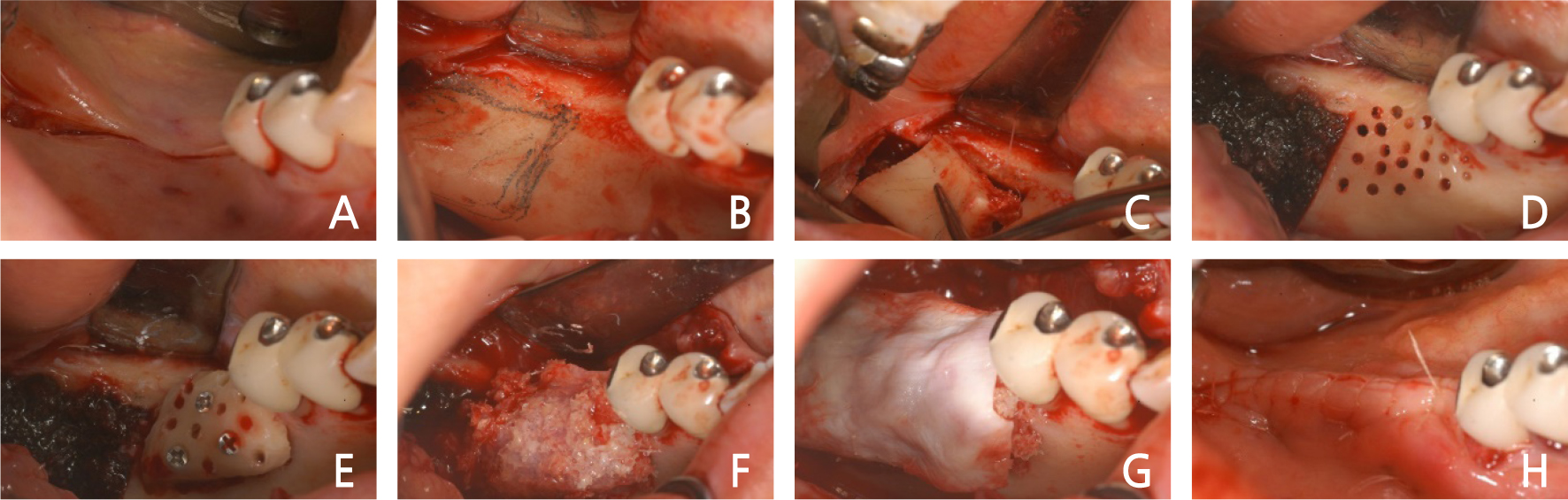
Fig. 18.
Case III: Intraoral views of autogenous ramal block bone graft surgery (right). (A) Incision of the surgical site. (B) Full-thickness flap was elevated. (C) Corticotomy and harvest of autogenous block bone. (D) Donor site with a hemostatic agent and recipient site preparation. (E) Fixation of block bone. (F) Addition of particulate allograft. (G) Absorbable membrane used. (H) The flap was sutured.
Three months after the block bone graft on the right bone defects, a block bone graft was operated on the left bone defects. Similar to the site on the right, after local anesthesia on the left surgical site in which the bone was absorbed vertically (Fig. 19A), the flap was elevated after an incision was made (Fig. 19B). After the cortical bone was cut using a piezoelectric device, a block bone measuring 2-cm wide, 1-cm long, and 4-mm thick was harvested (Fig. 19C). Similar to the site on the right, to reduce the hemorrhage on the donor site, a hemostatic agent was used, and recipient site preparation was made by boring a hole on the donor site (Fig. 19D). Using a microscrew, the block bone was fixed to the donor site (Fig. 19E). Additionally, a particulate allogeneic bone was used (Fig. 19F), and after it was covered well using an absorbable collagen membrane (Fig. 19G), it was sutured well using a horizontal mattress suture (Fig. 19H).
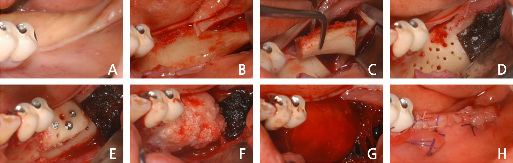
Fig. 19.
Case III: Intraoral views of autogenous ramal block bone graft surgery (left). (A) Pre-operative clinical gingiva. (B) Full-thickness flap was elevated. (C) Corticotomy and harvest of autogenous block bone. (D) Donor site with a hemostatic agent and recipient site preparation. (E) Fixation of block bone. (F) Addition of particulate allograft. (G) Absorbable membrane used. (K) The flap was sutured.
On the postoperative panoramic view, it was noted that the vertical block bone graft was well placed on the bone loss region approximately 4–5 mm vertically to the mandibular molar on both sides (Fig. 20).
Ⅲ. Discussion
After mandibular molar tooth loss, bone loss occurs, which sometimes leads to difficulty in placing a dental implant. In particular, for patients with mandibular removable partial dentures, severe vertical bone loss occurs. For dental implant placement, there is usually insufficient mandible remaining vertically to the inferior alveolar nerve; thus, vertical bone augmentation is needed.
As regards bone graft techniques for dental implant surgery of bone defect areas, there are various methods, such as guided bone regeneration, alveolar ridge splitting technique, and block bone graft. However, to graft the bone vertically, it is advantageous to use the autogenous block bone grafts that can maintain the form well after bone augmentation.
In addition, since the autogenous block bone graft maintains a hard shape after bone augmentation, it can be selectively used if stability in the reconstruction site is needed. It can be used much more favorably than the other bone grafting methods, especially in the reconstruction of bone defects that lose continuity.
Autogenous bone grafting to supplement the lack of bone mass in osseointegrated implant placement has been performed since bone grafting using the iliac bone was first discussed by Brånemark et al. in 1975.6 Since then, many surgeons have reported on the use of autogenous block bone grafts.
In 1995, Block et al. proposed that cortical and trabecular bone block is advantageous because it gives structural rigidity and provides growth factors and osteoblast.7 They also reported cases of placing implants , harvesting autogenous block bone from the iliac bone and the mandible anterior region, and conducting bone augmentation on the maxillary sinus and the upper alveolar bone. The iliac bone, rib bone, and tibial bone of endochondral origin have been used as regions where the autogenous bone is harvested. However, unless there is a big bone defect like implant surgery, it is preferable to use intramembranous bone and intraoral autogenous bone, where the volume of harvesting is limited. Nevertheless, fast harvesting is possible without postoperative defects and fewer occurrences of postoperative complications; thus, intraoral autogenous bone is often used in the reconstruction of the region with vertical and lateral bone losses for implant surgery.
Pikos harvested block-shaped autogenous bone from the mandibular symphysis and mandibular ramus external oblique ridge and used the autogenous bone block in the oral cavity.8 Pikos noted that placing an implant by 4 or 5 months after grafting autogenous block bone enhances the volume and quality of the bone and guarantees better early implant stability, and reported that the success rate of bone graft was 99% and the infection rate was less than 1% in a 5-year study.
Sethi and Kaus harvested and used block-shaped autogenous bone from the mandible to graft alveolar bone defects and placed 118 implants in 60 patients, showing a success rate of 98% and indicating the usefulness of mandibular block-shaped autogenous bone for the restoration of alveolar bone defects.9 They were divided into three parts according to the type of the site with vertical and lateral bone deficiencies, namely lateral loss, vertical loss, and vertical and lateral losses, and bone augmentation was performed using the mandibular symphysis and retromolar cortical blocks.
In the above cases, the region of bone defects was on the mandibular molar area. In type III bone deficiencies as classified by Sethi, which have a vertical and lateral bone deficiency, a block bone was harvested from the region posterior to the sites with vertical and lateral bone deficiency, the mandibular ramus, and the retromolar area. Since the autogenous bone block was harvested from the same regions, no additional surgical site was created for donor site harvesting. Thus, harvesting and bone augmentation were performed on a single site, shortening the operation time and reducing postoperative complications, leading to faster healing and less postoperative discomfort for the patient.
Khoury and Hanser harvested block bone from the oblique ridge of the mandibular ramus using a disc wheel in corticotomy to harvest the autogenous bone block.10 They reported that there were fewer complications at the donor site and many block bone grafts were successful since they performed corticotomy with minimal trauma to the tissues using the disc wheel.
In Case 1 and Case 3, when the corticotomy was performed in the mandibular ramus and mandibular retromolar area, it was possible to harvest the block bone by cleanly cutting the cortical bone without any damage to soft tissues, using a piezoelectric device and a disc wheel as Khoury did.10
In addition, Frost noted that applying a harmful stimulus called regional acceleratory phenomenon (RAP) by boring a hole or applying a stimulus to the recipient site leads to a more effective process of the formation of tissues two to ten times faster when the bone is cured.11 He also noted that the cortical bone and the growth factors in the cortical bone play important roles in osteogenesis. In addition, Cordaro et al. harvested block bones from the mandibular ramus or mandibular symphysis in a patient with a partially edentulous jaw, operated a lateral or vertical onlay block bone graft in the bone defect region, and fixed them with a titanium screw.12
In the above cases, the blood supply was facilitated by decortication by boring a hole in the recipient site for faster tissue regeneration, and osteogenesis was accelerated as the RAP was formed. While a block bone is grafted on the mandible with thick cortical bone, there is a possibility that bone augmentation may fail as the transplanted block bone is not grafted well if the recipient site is not prepared properly. In addition, to fix the harvested block bone to the region with vertical and lateral bone defects after completion of the recipient site preparation, the graft was firmly fixed, using at least two microscrews to prevent the micro-movement of the grafted block bone so that no fibrillar connection would occur, and the firm fixation was performed so that the block bone graft would be successful.
After the augmentation of autogenous block bone, there was edema and ecchymosis. However, there was no infection at the surgical site or serious complications, such as fall of transplanted splinters of the bone. Seven months later, when the regions of block-shaped autogenous bone were exposed to place the implants, blood supply and engraftment at the recipient site were fine.
Ⅳ. Conclusion
In these clinical cases, bone augmentation was required because implant surgery was difficult due to vertical bone deficiency in the mandibular posterior region. Therefore, the possibility of esthetically and functionally successful implant surgery was achieved by delaying implant placement by grafting block bone in the region with vertical and lateral bone deficiencies. This was performed by harvesting autogenous block bones in the mandibular ramus and retromolar area in the same posterior region.
