

Ⅰ. Introduction
Ⅱ. Materials and Methods
1. Components of implant surgery robot
2. Fabrication of human phantom
3. Implant planning and surgical guide stent
4. Tracking accuracy
5. Accuracy measurement of implant position
6. Statistical analysis
Ⅲ. Results
Ⅳ. Discussion
Ⅴ. Conclusion
Ⅰ. Introduction
Robots are automatically operated machines that have replaced humans in performing various tasks. With advancements in robotic technology, a robotic system, the da Vinci Robot (Intuitive Surgery, Sunnyvale, CA, USA), has been gaining popularity for helping surgeons deliver a less invasive approach in the medical fields across gynecology, urology, and general surgery.1,2 Proven advantages of robotassisted surgery include precise execution of technically demanding procedures and elimination of human tremors.2
Among their various applications in the dental field, robots have been successfully implemented in implant surgery.3,4,5 Dental implants should be placed at a prosthetically desired position for the longevity of the implant and prosthesis because inaccurate placement may cause clinical complications, such as damage to adjacent teeth, nerves, and blood vessels, as well as periodontal and esthetic problems.6,7,8 With the increased use of cone beam computer tomography (CBCT) in dental practice, implant surgical guides are recommended for correct implant placement following comprehensive virtual implant planning. Compared to the freehand approach, CBCT-generated guide stents provide greater accuracy for placing implants at the desired pre-planned positions, leading to predictable outcomes.9,10,11,12
In robot-assisted surgery, the direction of the surgical handpiece attached to the robot arm is continuously monitored and dynamically controlled using an optical tracking device based on the preplanned coordinate transformation algorithm. Robot-assisted implant surgery has shown deviation values similar to those of static guided surgery, validating the feasibility of robot-assisted implant surgery.3,4,5,13 Despite the recent promising potential applications of robot-guided implant surgery, previous studies did not directly compare the accuracy of the robots with that of CBCT-generated guide surgery within the same setting.
Therefore, the purpose of the present study was to evaluate the tracking accuracy of a robot-guided implant surgery system and to compare the performance of robot-assisted implant surgery with that of static-guided implant surgery using a surgical guide stent. The null hypothesis was that the accuracy of implant positioning does not differ between robot-assisted and traditional guided implant surgery.
Ⅱ. Materials and Methods
1. Components of implant surgery robot
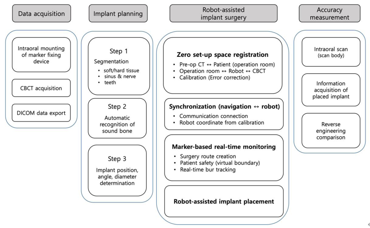
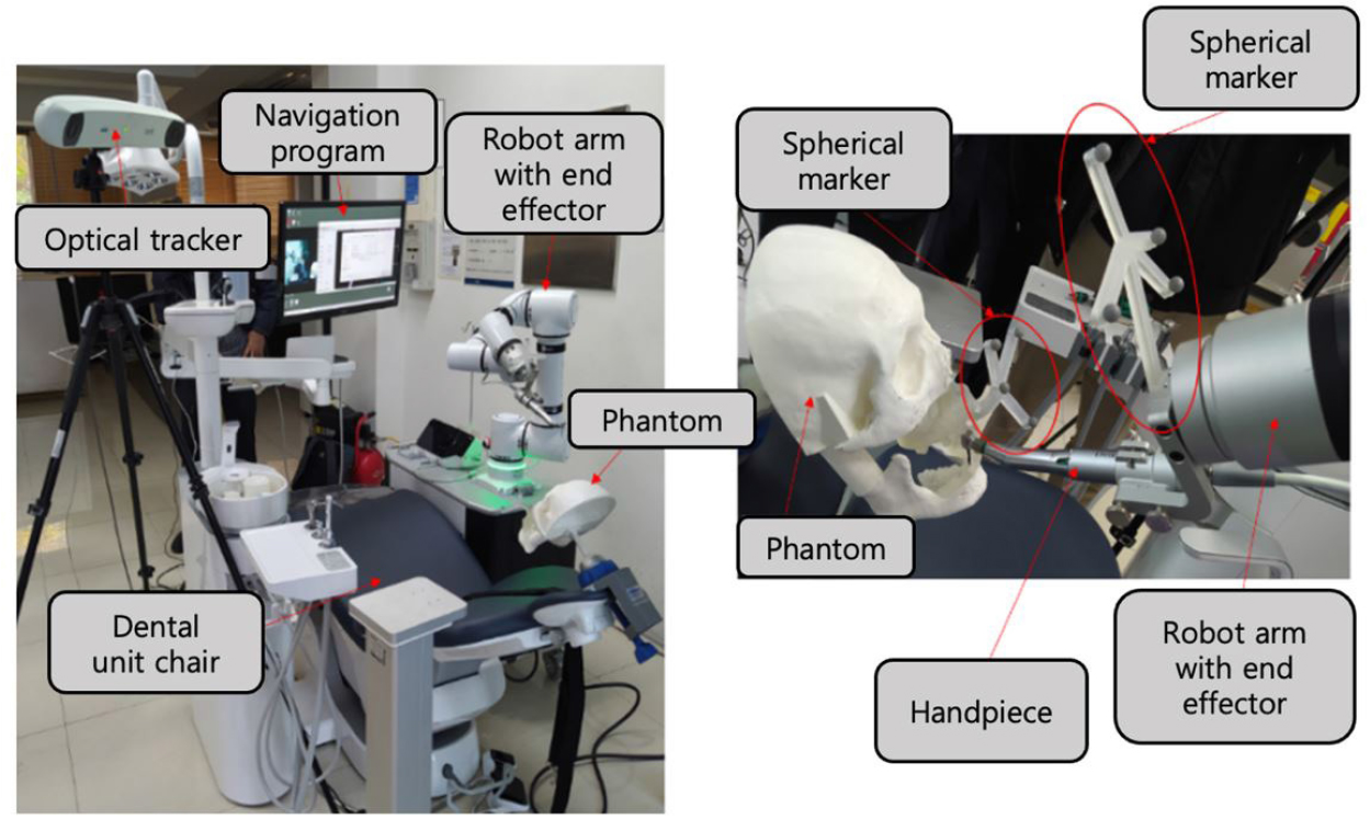
The workflow of the robot-assisted implant surgical system and the accuracy evaluation procedure are shown in Fig. 1. The implant surgical robot system consisted of a robot arm (Puloon, Seoul, Korea), robot operating software (MI2RL, Seoul, Korea), optical tracker (Polaris Vega; NDI, Waterloo, Canada), and positioning markers (Fig. 2). The robot arm had a working range of 850 mm with six degrees of freedom, load capacity of 5 kg, and position repeatability of ±0.1 mm. The optical tracker had a maximum frame rate of 250 Hz, with a volumetric accuracy of 0.12 mm. Four spherical markers (OptiTrack M3 Marker; NaturalPoint Inc., Corvallis, OR, USA) were connected to the implant handpiece and four to the patient device. The marker-fixing device mounted in the patient’s mouth consisted of an intraoral securing part and an extraoral marker-supporting part. The marker-fixing device mounted on the robot arm was designed to have a handpiece-securing part and a marker-supporting part.
2. Fabrication of human phantom
The human phantom was fabricated using a 3D printer (Form3; Formlabs Inc., Somerville, MA, USA) using datasets of spiral CT scan, intraoral scan (i500, MEDIT Corp., Seoul, Korea), and facial scan (Arc-4, Bellus3D, Campbell, OH, USA) from one of the researchers of this study. After aligning the multimodal datasets, the teeth in the right mandibular canine and premolars, where implants were planned to be placed, were removed, and the marker-fixing device on the phantom was positioned to simultaneously print the phantom with the marker-fixing device in one piece.
3. Implant planning and surgical guide stent
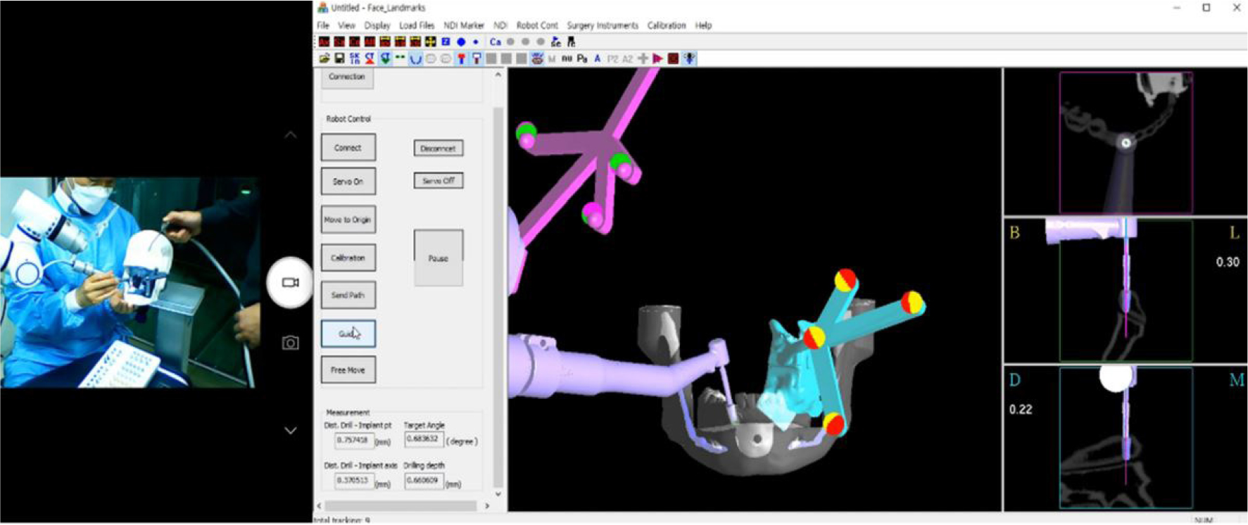
Implants were placed using two methods: robot-assisted surgery and surgical-guided surgery. The position of the implant was set in the implant planning software [MI2RL for the robot group (Fig. 3), and Implant Studio (3shape A/S, Copenhagen, Denmark) for the surgical guide group] using the DICOM data obtained from a CBCT (DENTRI; HDXWILL, Seoul, Korea) scan of the printed patient phantom. An internal connection implant (TSIII; OSSTEM IMPLANT Co. Ltd., Seoul, Korea) of 4.5 mm width and 10 mm height was used. After designing the sleeve part of the surgical guide using the sleeveless library, the surgical guide was 3D printed with clear resin (Dental LT Clear Resin; Formlabs Inc.).
4. Tracking accuracy
To evaluate the tracking accuracy of the robot system, the accuracy of the twist drill mounted on the robot arm-fixed handpiece was analyzed by repeatedly and accurately reaching the top of the implant. After the handpiece of the robotic arm was accurately positioned at the top of the implant, the pose of the robotic arm was saved. The robot arm was moved to 20 different positions at various angles and then returned to the saved position. The coordinates of the twist drill end and the dill angulation were recorded in the robot operating software followed by measurement of the discrepancy between the position of the robot arm and the actual saved position.
5. Accuracy measurement of implant position
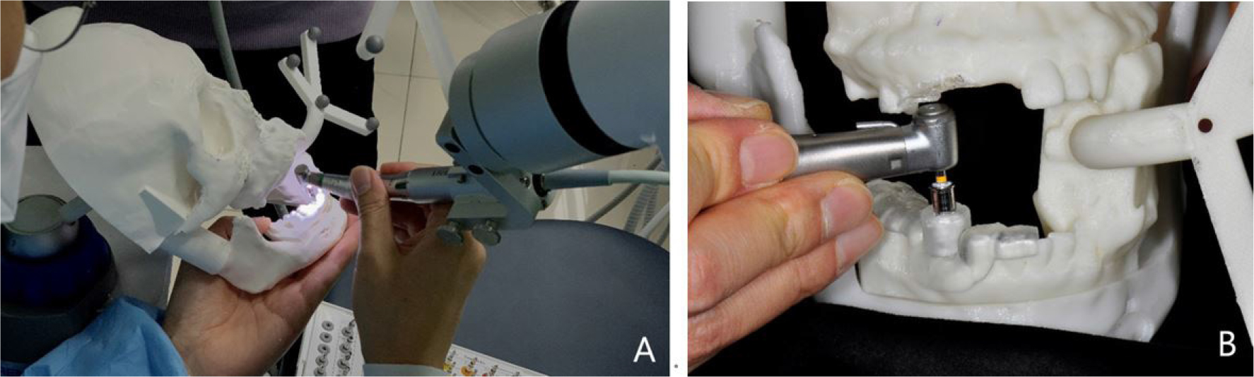
To compare and evaluate the implant placement accuracy of the robotic system and the implant guide system, implant surgery was performed according to the manufacturer's instructions for each group (Fig. 4). In the robot group, calibration was performed based on the position of the tip of the twist drill expressed by the optical tracker. Drilling was performed according to the conventional implant drilling protocol, followed by implant placement with an implant driver using an implant engine (Wireless iCTmotor; Dentium, Seoul, Korea) (n = 4). In the surgical guide group, the implants were placed with the same implant engine and handpiece used in the robot group, with the aid of a surgical guide stent (n = 10).
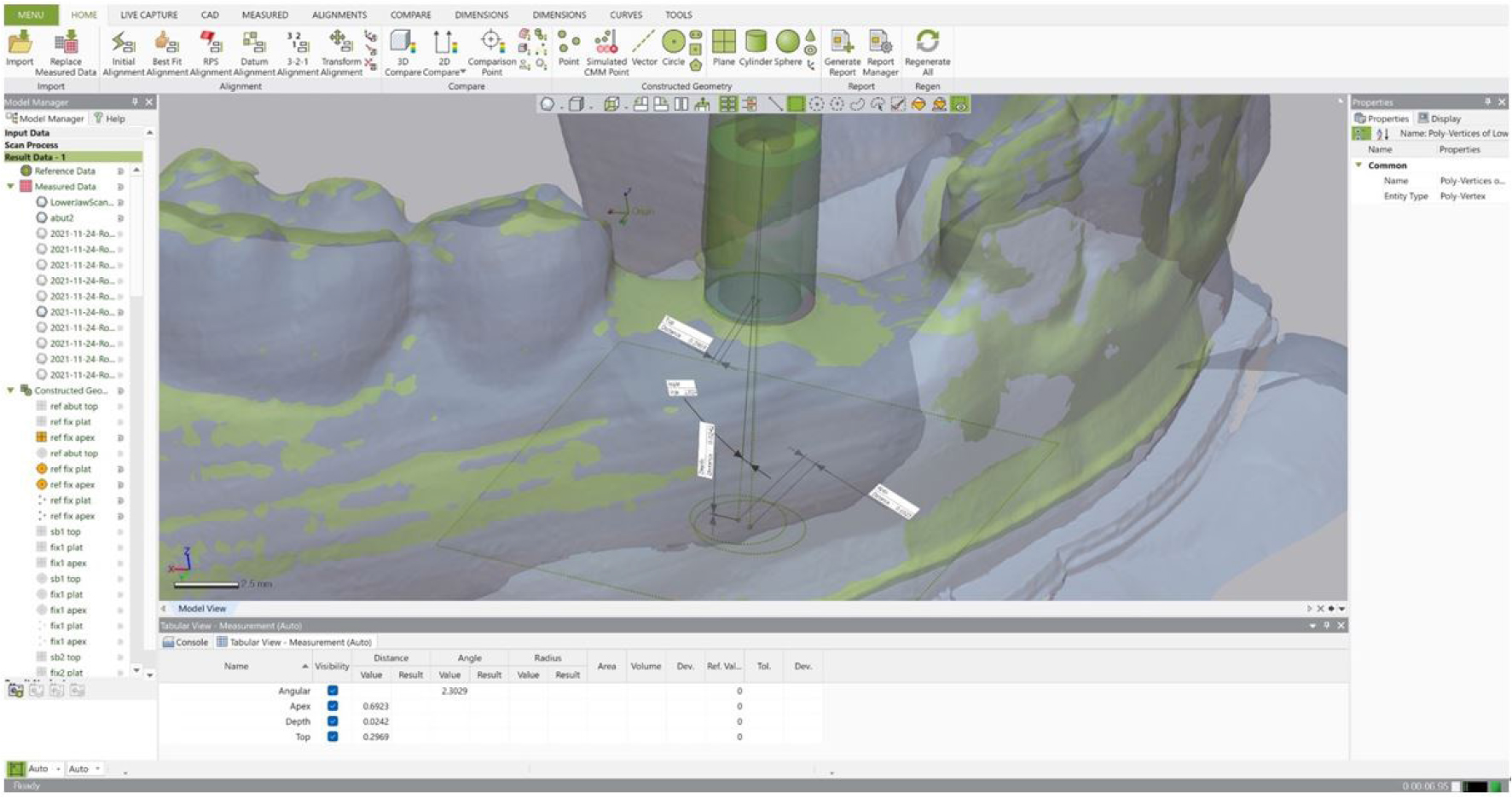
The accuracy of the implant position was measured using a three-dimensional metrology software (Geomagic Control X; Ver. 2020.1, 3D Systems Inc., Rock Hill, SC, USA). The phantom was scanned using an intraoral scanner (i500; MEDIT Corp.) with the scan body (Geodent SURO; GeoMedi Co. Ltd., Uiwang, Korea) placed on the implants. The scanned data were aligned with the implant planned model using the best-fit algorithm. Angular and linear deviations at the top and apex of the implants were measured. Depth deviation was obtained by measuring the vertical discrepancy at the apex of the placed implants compared with the planned position (Fig. 5).
6. Statistical analysis
Levene’s test was used to assess the homogeneity of variances, and the normality of the data distribution was tested using the Shapiro–Wilk test. The top, apex, angular, and depth deviations of the robot and surgical guide groups were compared using the Mann-Whitney U test for pairwise comparisons. Statistical analyses were performed using statistical software (SPSS version 26.0, IBM, Armonk, NY, USA) at a significance level of .05.
Ⅲ. Results
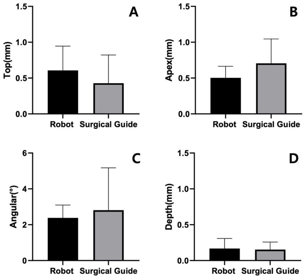
The tracking accuracy of the robot system while changing the position of the end device showed a mean linear deviation of 0.13 ±0.04 mm and angular deviation of 0.77 ±0.02° at the drill tip. Figure 6 shows the mean deviations of the implants placed relative to the planned position. The mean linear deviation at the top of the implants was 0.61 ±0.29 mm and 0.49 ±0.39 mm in the robot and surgical guide groups, respectively. Mean linear deviations at the apex of the implants were 0.50 ± 0.14 mm and 0.72 ± 0.34 mm in the robot and surgical guide groups, respectively. The mean angular deviation was 2.38 ± 0.62° in the robot group and 3.16 ± 2.36° in the surgical guide group. The depth deviation of the implants relative to the planned implant depth were 0.17 ± 0.12 mm in the robot group and 0.15 ± 0.11 mm in the surgical guide group. The difference in none of the top, apex, angular, or depth deviations was statistically significant between the robot and surgical guide groups (p > .05).
Ⅳ. Discussion
The discrepancy in the implant top, apex, angle, and depth relative to the planned implant position was statistically insignificant in both groups. Therefore, the null hypothesis was accepted, and the alternative hypothesis was rejected. Although a statistically significant difference was not found, the mean deviation of the surgical guide group at the implant top was small, and the standard deviation was narrow. In contrast, at the apex, the mean deviation was small in the robot group, and the standard deviation was narrow. This may be because the target mechanisms of the two groups were different. The sleeve of the computer-guided implant surgical template controlled the accuracy in the surgical guide group. The sleeve was designed on the top of the implant with a fixed offset after the implant position was determined in the implant planning software. The sleeve is 3D printed as wide as the tolerance determined by the program for the inner wall, such that the guide drill contacts it and precisely cuts the alveolar bone at the planned position, angle, and depth within the cylindrical sleeve. Therefore, there is a high possibility that the implant top, close to the sleeve, is most accurately positioned.
In contrast, in the robot group, the target of accuracy is the tip of the twist drill and the apex of the implant. As the end effector of the robotic arm in the robot system, the implant engine and handpiece are connected, and the shape of the handpiece and drills used are embedded in the robot control software library. In addition, the positional relationship between the spherical markers on the rigid body mounted in the patient's mouth and the markers connected to the handpiece of the robotic arm are tracked in real time by the optical tracker. The drilling sequence of the robot manipulation software programmed on the robot operating system moves the robot end effector to its initial position in front of the patient's mouth, and then the dentist holds the handpiece and turns it according to the planned implant axis. The operator moves the handpiece along the virtual wall while providing haptic feedback to position the drill tip. Subsequently, the axis of the twist drill is aligned, and implant drilling is performed in a state where only vertical movement is possible while maintaining the implant axis. After the end effector has reached its initial position, the dentist controls the handpiece movement and implant engine rotation. However, restrictions on the movement of the robot arm are applied along the virtual wall created based on the implant planned using the robot manipulation software, thereby offsetting the dentist's hand tremors or sudden movement of the patient and assisting osteotomy in the planned position, direction, and depth. Because the twist drill tip is the target of accuracy in the robot group, the accuracy is the highest at the implant apex. On the other hand, deviation at the implant top can be affected more by the patient's movement or other variables during surgery.
A few research teams in China have combined the UR5 robot from Denmark with an optical tracker from Canada for implant surgery. Xie et al. performed an in vitro study on automatic implant placement and reported top/apex deviations of 0.705/0.998 mm,14 and Liu et al. reported top/apex deviations of 0.79/1.26 mm in a phantom study.3 Wu et al. placed a 50-mm zygomatic implant in the phantom and reported top/apex deviations of 2.34/0.79 mm in 2018 and of 0.79/1.49 mm in 2020.4 On the other hand, the Yomi robotic system was approved by the FDA 510(k) in the United States in 2020, and 1000 implants were placed by 2019. A clinical study was conducted using this system, and 38 implants were placed in 5 patients. Top/apex deviations of 1.04/0.95 mm were reported.5 The implant top/apex deviation in the robot group in this study was 0.61/0.5 mm and slightly less than that in previous studies. This may be caused by differences in the experimental settings of the in vitro study. This also seems to be because the manufacturing of the phantom and the robot system's tool calibration were strictly performed to minimize error. In addition, the robotic arm was optimized with the necessary payload and robot control algorithm based on the literature on robot-assisted implant surgery.
There was no statistically significant difference in angular deviation, but the standard deviation was greater in the surgical guide group. In the robot group, the robot manipulation software continuously tracked the position between the patient and handpiece and maintained the planned implant axis. In contrast, in the surgical guide group, an angular error was allowed owing to the tolerance between the sleeve and drill. Park et al. compared the angular deviation of the twist drill in the sleeve of the metal sleeve and sleeve-free systems.15 The former ranged from 2.96° to 4.71°, and the latter was 2.28°, smaller than the 3.16° measured using the metal sleeve-free guide template in this study. Oh et al. measured the degree of diversion of a twist drill in a metal sleeve-free guide manufactured by 3D printers of various manufacturers on a fully edentulous model and reported values of 3.45°–6.55°.16 This study showed a slightly larger value than the results of the present study. Because the movable angle is reduced when the drill rotates, it is expected that the results will be similar. The same research team evaluated the angular deviation of implants placed on a partially edentulous model.17 The angular deviation in the metal sleeve-free group was 0.61–1.62° and was less than that in the present study, under the same conditions. This seems to be due to the difference in the guide stability during surgery. Systems using metal sleeves tend to have tolerance; however, recently, metal sleeve-free systems with small angular errors have been preferred because of their small tolerances. Xie et al., who conducted an in vitro study using the UR5 robot system, reported a deviation of 2.077°,14 Liu et al. of 3.77°,3 and Wu et al. of 1.52°.4 In a clinical study using the Yomi system, an angular deviation of 2.56° was reported.5 These results are consistent with those of our study.
Errors in the guide system are cumulative and are added at each manufacturing stage. Valente et al. mentioned errors occurring in guides for implant surgery.18 An error of less than 0.5 mm may occur during the CT scan and image reconstruction process, and an error of 0.1 to 0.2 mm may occur during the template manufacturing process. Moreover, errors of various sizes can occur during template delivery and drilling, depending on the system.18 As twist drills must move up and down smoothly inside the sleeve, a unique tolerance is given to each system. Assuming that the sleeve height is 5 mm and the tolerance is set such that the inner diameter of the sleeve is 0.15 to 0.2 mm wider than the drill, theoretically, the drill can move within the sleeve at an angle of 2.3°. At a position 20 mm away from the sleeve in the apex direction, the deviation is about 1 mm, and it is a value corresponding to the third quartile of the apex deviation in the surgical guide group of this study. However, because the angular deviation is reduced when the twist drill is rotating, the actual angle of the drill hole after drilling, and hence, the angle of the implant, will be smaller than the theoretically calculated value. As the drill for the guide system is usually long, the twist drill cannot access the sleeve of a patient with a small mouth opening. In this case, human error may occur during manual drilling, such as incorrectly fitting the bur stop or drilling deeper than planned due to incorrect calculation of the drill depth. When using the robotic system, the surgeon can use a general-type drill that is as short as the length corresponding to the sleeve of the guide, and precise drilling is possible in a short time when the patient opens the mouth as much as possible.
Although the dynamic navigation system was not evaluated in this study, it can be said that it is the same as the dynamic navigation system if it is operated with optical tracking, markers, and software, except for the robot manipulator element. Jorba-García et al. reported in their meta-analysis examining 24 papers targeting nine types of navigation systems that there were top/apex deviations of 0.74/1.09 mm. 19 Compared with robot-assisted surgery, uncertainty in accuracy data tends to be high because of unexpected variables such as operator error, hand tremors, and sudden movement of the patient. The small apex deviation of the robotic system is a clinical advantage. When anatomical structures are close, accuracy of the drill tip position and depth is essential for safety.
The depth of drilling is crucial in surgery to prevent invasion of anatomical structures. A depth deviation of 0.42 mm was reported in a clinical study performed with the Yomi system and was calculated as 0.66 mm in a meta-analysis on dynamic navigation by Jorba-García et al.5,19 In this study, it was 0.17 mm, which was slightly smaller than that reported in the previous studies, which may be attributed to the lack of various emergencies that occur in an actual clinical setting. In the robot system, the drilling depth is adjusted according to the position of the twist drill tip tracked by the optical tracker, and the virtual wall restricts movement deeper than the planned depth to protect the anatomical structures. There is an extended rim in guide surgical drills, which is caught at the top of the guide hole, preventing deeper drilling. Both systems do not allow deeper movement, preventing injury to anatomical structures; however, there may be exceptions in actual clinical practice. When inserting an implant using an implant mount after bone preparation with a twist drill and screw tap, the entire implant may not be inserted even if the engine's maximum torque is applied owing to inadequate bone or hardness of the bone. Therefore, the implant is manually inserted to the final depth. In this study, depth deviation was calculated as the average of the absolute values. However, there were cases where the implant was placed deeper than the target depth, up to 0.34 mm in the robot group and 0.13 mm in the surgical guide group. It seems that this was caused by operator error when using the hand ratchet. Measures for depth indicators are needed to prevent this accident. There are implant surgical guide systems that can match the implant depth and rotating position by matching the notch of the sleeve by indicating the mark of the implant mount with color. However, the currently introduced dental implant robot system does not introduce functions, such as adjusting the degree of bone preparation or the torque of the implant engine according to the bone quality.
The limitation of this study is that the number of phantoms used to evaluate the robot system was limited; thus, sufficient data could not be obtained. A CMM-based mechanical tracker was used in the Yomi robotic system for sudden movement of the patient, but this was not reflected in this study. Future research is necessary to evaluate a robot system with a mechanical tracker for implant placement in a phantom that moves randomly, similar to a real surgical environment.
Ⅴ. Conclusion
In the limited experimental environment, the following conclusions were drawn. There was no difference in the implant placement accuracy of robot-assisted and static-guided implant surgeries. The robotic system tended to show fewer deviations at the implant apex and guide system at the implant top. The robotic system is expected to help dentists perform accurate and safe implant surgery in future owing to its advantages, such as short surgery preparation time, possibility of changing the plan during surgery, and prevention of operator errors.
