

Ⅰ. Introduction
Ⅱ. Materials and Methods
1. Model Fabrication
2. Reference Data Acquisition
3. Scan Data Acquisition
4. Calculation of Data Coordinates and Distances
5. Statistical Analysis
Ⅲ. Results
1. Effect of the Intraoral Position
2. Effect of the Types of Digital Impression Coping
Ⅳ. Discussion
Ⅴ. Conclusion
Ⅰ. Introduction
The computer-aided design and computer-aided manufacturing technology used in dentistry has significantly advanced over the past 20 years and has been widely researched and applied in clinical practice across the entire field of dentistry. Computer-aided technologies allow for more accurate and effective processes that can reduce the burdensome steps of both chairside and laboratory work, thus saving working time.1,2,3 The application of these technologies is steadily growing in the field of prosthodontics including fixed, removable and implant prosthodontics.
Conventional fabrication of implant prostheses is a complex and stressful process for both clinicians and patients. The conventional method of implant fabrication involves the use of transfer or pick-up copings, which are either long or uncomfortable for patients, particularly when placed in the posterior region or for those with limited mouth opening.4,5,6
Digital implant impressions obtained using an intraoral scanner may provide a convenient solution to overcome the disadvantages of conventional methods. Scanned data is obtained from digital impression copings; however, the length of these digital impression copings is shorter than that of the conventional impression copings, resulting in reduced discomfort for the patient. Moreover, digital impression makes the process easy for patients who are undergoing orthodontic treatment, or those who have undercuts or tooth mobility caused by periodontal disease.7,8
Usually, when obtaining digital scans of implants, the healing abutment is removed, and the scan body is connected to the installed implant fixture. An accurate fit between the scan body and implant fixture is critical when performing this procedure. Further, repeated removal and connection of the healing abutment and scan body can damage the tissues surrounding the implant, and alter the shape of the gingival margin, making it difficult to obtain accurate scan data.9 Depending on the bone and gingival status of the patient, the implant may be placed in a deep position. In such cases, the patient may feel discomfort during the process as the scan body or healing abutment is being connected. Furthermore, patients may experience discomfort during the procedure when the scan body is positioned higher than the occlusal plane, particularly in the posterior region.10
An encoded healing abutment, which includes a separate screw connected to the implant fixture, has recently been introduced to overcome the shortcomings of the scan body. The scan pin can be attached to the top of the encoded healing abutment, although in certain implant systems, a scan pin may not be existed. The encoded healing abutment contains the necessary information to design the implant prosthesis, such as the platform diameter and implant hex position.11,12 Therefore, encoded healing abutments allow intraoral scanning to be performed directly after their placement, depending on the gingival status, on the day of the second surgery (uncovering) procedure. In other words, an encoded healing abutment does not require removal for intraoral scanning, unlike when scanning is performed with a scan body. Additionally, this method can potentially reduce the problem of misengagement during fixture-level impressions.12
Therefore, the purpose of this in vitro study was to investigate the accuracy and effect of the position of the scan body and the encoded healing abutment in the digital intraoral scanning of implants.
Ⅱ. Materials and Methods
1. Model Fabrication
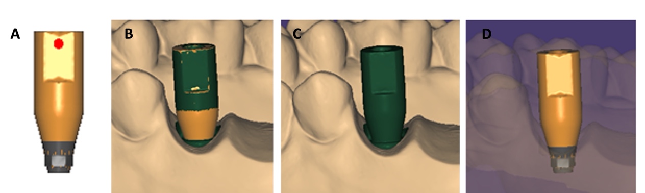
A maxillary stone model was fabricated from Dentiform Model 400 (Hanil Dental, Gyeonggi-do, Korea) using CharmFlex UltraLight (Dentkist, Gyeonggi-do, Korea) and CharmFlex Heavy (Dentkist) impression materials along with dental stone (Hinriston® 20; ERNST HINRICHS Dental GmbH, Goslar, Germany). After the right second premolar (#15), first molar (#16), and second molar (#17), and left central incisor (#21) were removed from the stone model using a denture bur, a hole was made to place and fix the scan body (ISLA500; Neobiotech, Seoul, Korea) at tooth positions of #15,17 and 21 (Fig. 1). The scan body fixed to the stone model was scanned with a model scanner (Medit Identica Hybrid; MEDIT Co., Seoul, Korea), and the scanned data was imported into Exocad DentalCAD (Exocad GmbH, Darmstadt, Germany) to create a digital laboratory analogue file for each of the three tooth positions (#15, 17, 21). Subsequently, a three dimensional (3D) printed resin model with a digital laboratory analogue (Neobiotech) was fabricated using a ZENITH L 3D printer (DENTIS, Daegu, Korea) (Fig. 2A).

2. Reference Data Acquisition
After the scan body (IS D5; Neobiotech) was connected to the model on #15i, #17i, and #21i, it was scanned using a model scanner (Medit Identica Hybrid; MEDIT Co.) and the element hex was created using Exocad (Exocad GmbH) (Fig. 2B). Data were saved as STL files and used as the reference data.
3. Scan Data Acquisition
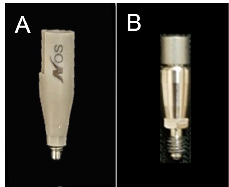
To compare the scan body and encoded healing abutment, scan data were obtained using a Trios® (3Shape Dental Systems, Copenhagen, Denmark) intraoral scanner. The scan body (IS D5) which was 5.0 mm in diameter and 14.1 mm in length, was connected to tooth position #15i, 17i, and 21i of the model, and scanning was performed and repeated 20 times.
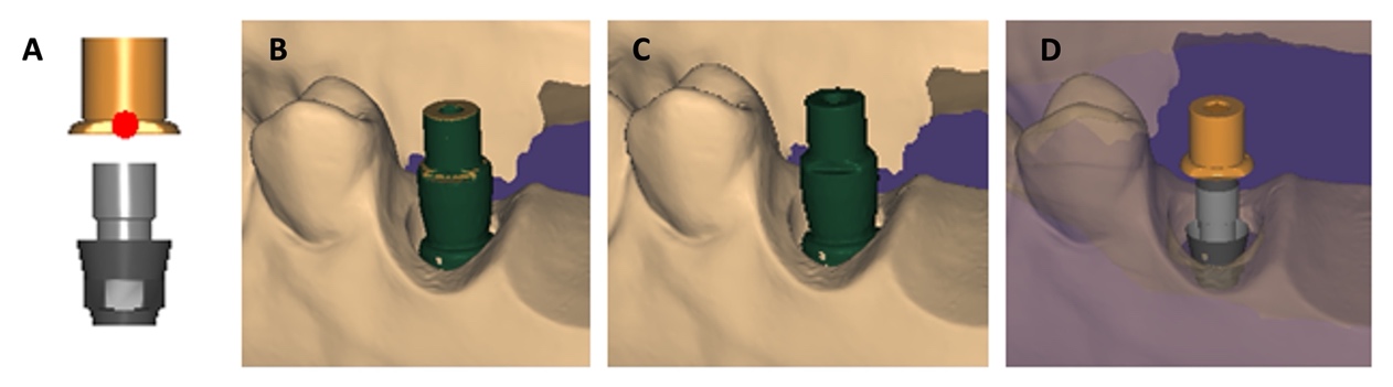
The encoded healing abutment (IS 4004S; Neobiotech) which was 4 mm in diameter and 4 mm in length, was connected to the #15i, #17i and #21i positions of the model. A scan pin was then connected to the top of the coded healing abutment for scanning following the same procedure as with the scan body (Fig. 1). All the scanned data were converted into an STL files (Figs. 3 and 4).
4. Calculation of Data Coordinates and Distances
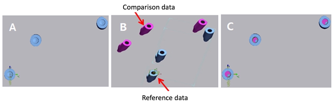
Geomagic® Control X (3D Systems, Rock Hill, South Carolina, USA) was used to compare the scan data of the scan body and encoded healing abutment, with the reference data. The x, y, and z coordinates were positioned at the center of the #17i hex of the reference data, while the coordinates for the #15i and #21i were calculated and designated as the reference coordinates. The data obtained from the intraoral scanner were imported together with the reference data and aligned using the initial and best-fit alignments, after which the coordinate values were derived by establishing the same coordinates. The distances between the reference coordinates and the x, y, and z coordinates for #15i, #17i, and #21i were determined. The Euclidean distances between the coordinates was calculated as the following formula. (Figs. 5 and 6).
Euclidean distance =

5. Statistical Analysis
All statistical analyses were performed using R Ver 3.6.2 (R Foundation, Vienna, Austria). A two-way analysis of variance was performed to compare the two types of digital impression copings and intraoral tooth positions. In addition, an independent t-test was performed to investigate the differences between the two types of impression copings. The significance level was set at p < .05.
Ⅲ. Results
1. Effect of the Intraoral Position
Analysis of the mean distance differences from the reference coordinates with the two impression coping types and the intraoral positions (#15i, #17i, and #21i) as variables demonstrated significant differences between the two types of impression copings (p < .001). However, the intraoral positions did not influence the results (p = .1315). Examination of the influence of both types of impression coping and the intraoral positions on each other revealed no significant difference in the mean distance measured between the two impression coping types, even with variations in the intraoral positions (p = .0711) (Table 1). In addition, no significant differences were observed in the mean distance according to the intraoral positions for each type of impression coping (Tables 1 and 2).
Table 1.
Differences in distance according to the experimental group and tooth position
| Factor | F Statistics | p-value |
| Impression coping | 16.435 | < .001 |
| Intraoral position | 2.066 | .1315 |
| Interaction | 2.706 | .0711 |
Table 2.
Mean and standard deviation of distance difference according to the experimental groups and intraoral position (Unit: mm)
| Group | Intraoral position | N | Mean ± SD |
| Scanbody | 15 | 20 | 0.067 ± 0.045 |
| 17 | 20 | 0.135 ± 0.032 | |
| 21 | 20 | 0.064 ± 0.057 | |
| Encoded healing abutment | 15 | 20 | 0.299 ± 0.368 |
| 17 | 20 | 0.199 ± 0.141 | |
| 21 | 20 | 0.153 ± 0.139 |
2. Effect of the Types of Digital Impression Coping
As the intraoral positions did not influence the results, position variables were excluded. The mean differences in distance from the reference and both types of impression copings are shown in Table 3. After excluding the position variables, 60 datasets were analyzed. The mean difference in the distance from the reference was 0.089 mm for the scan body and 0.217 mm for the encoded healing abutment. In other words, the distance from the reference was shorter with the scan body than the distance with the encoded healing abutment, indicating that scanning with the scan body produced slightly more accurate results than those obtained with the encoded healing abutment.
Ⅳ. Discussion
The passive fit of an implant prosthesis is an important factor for the prognosis of prosthetic treatment, and for this reason, accurate impression-taking must precede the fabrication of the prosthesis.13 The accuracy of dental prostheses fabricated using an intraoral scanner has significantly improved.14 Intraoral scanning for the fabrication of an implant prosthesis involves removing the healing abutment placed during implant placement and subsequently connecting the scan body to the implant fixture to allow impression-taking with an intraoral scanner.
The scan body was the first system to be developed for digital impression-taking of implants and is now commonly applied in clinical practice. Many studies have since compared digital scans with conventional impression-taking techniques for prosthesis fabrication.15,16,17 Kim et al15 compared the accuracy of conventional impression-taking with pick-up impression coping to digital scanning with a scan body. The study revealed that the amount of displacement was 59.4 μm for conventional impression and 144.3 μm for digital scanning with scan body. This indicates that conventional fabrication using a stone model with a pick-up impression produces accurate results, but may introduce potential errors during the fabrication of the stone model.
If a scan body can fulfill the same function as an impression coping in conventional impression taking, then an encoded healing abutment can simultaneously play the role of a healing abutment and an impression coping. This allows for a single installation intraoral scan following implant placement for prosthesis fabrication.11 Encoded healing abutments contain installed implant information such as hex orientation, installed depth, and diameter of the implant platform. Although few studies have reported on the use of encoded healing abutments, Eliasson et al14compared the accuracy of an implant impression between encoded healing abutment and conventional pick-up coping, reporting that the 3D displacement was 31.2 μm for the pick-up impression and 79.5 μm for the scanning with encoded healing abutment. They further reported that the accuracy of scanning with the encoded healing abutment was sufficient for single implant impressions.
The present study aimed to compare digital impression-taking methods using a scan body and an encoded healing abutment, whereas most previous studies compared the accuracy of digital scans with conventional impression-taking methods. In addition, unnecessary errors were reduced by comparing data obtained from an intraoral scanner connected to a scan body, or an encoded healing abutment to a 3D printed model based on a fabricated plaster model. In a prior study, Flügge et al18 compared model scanners and intraoral scanners, reporting that the mean deviation was 10 mm for model scanners and 50 mm for intraoral scanners, indicating a higher accuracy of model scanners than that of intraoral scanners. Based on these findings, the scanned data obtained from the model scanner were used as reference data in the present study.
In another study, Gimenez et al19reported that the accuracy of intraoral scanning decreased as the amount of scanned data increased, as the scanner stored data by superimposing the scanned images. Meanwhile, Moreno et al20 further reported that the accuracy of impressions varied in the anterior region, where rotation of the dental arch occurred. Therefore, in the present study, three positions (#15i, #17i, and #21i) rather than a single position were used to compare the accuracy of scanning in both the anterior and posterior regions. As the scan started at the same position (#17i), the present study also aimed to evaluate the decrease in accuracy due to the superposition of the scanned data as the scan progressed towards #21i. In contrast to previous studies,19,20 this study found no significant difference in the mean distance with a scan body or encoded healing abutment according to the intraoral position, which was potentially attributed to the small amount of bias in the data. This is because the #15i and #17i positions were set at a relatively small distance from the bridge, and the experiment was performed utilizing a model designed to yield precise scan results when a scan body or encoded healing abutment was positioned at #21i.
The results of the present study indicated that the mean distance between the two experimental groups exhibited differences relative to the reference data, with the scan body demonstrating a higher accuracy than the accuracy observed with the encoded healing abutment. One reason for this may be the difference between materials. The scan body is made of polyetheretherketone (PEEK), whereas the encoded healing abutment is made of a metallic material. Therefore, less light scattering was noted during scanning with the PEEK than with the encoded healing abutment, which contributed to the high accuracy. Additionally, significant differences were also observed in the shape and length. The scan body was longer than the encoded healing abutment, which may have contributed to the higher scan detection rate than that of the healing abutment. The results of the present study did not reveal any significant differences between the two experimental groups, however, based on the results of previous studies14,15 comparing the accuracy of impression-taking methods, it was determined that the accuracy of the encoded healing abutment was also clinically acceptable.
This study has several limitations, including the fact that the experimental groups used different materials, and the experiment was not conducted in the oral environment. Despite these limitations, the importance of the present study is that it directly compared the accuracy of the scan body with that of the encoded healing abutment. Therefore, further studies involving the oral environment are required.
Ⅴ. Conclusion
The present study compared the scanned data obtained with both the scan body and the encoded healing abutment using an intraoral scanner, leading to the following conclusions:
1. No significant difference in either the scan body or encoded healing abutment groups was observed according to intraoral position.
2. The accuracy of scan data was higher with the scan body than with the encoded healing abutment.
