

Ⅰ. Introduction
In partially edentulous patients, implant-fixed prosthesis restoration is widely used as a preferred treatment method. There are screw-retained, cement-retained, and screwcement-retained methods for retaining implant-fixed prostheses.
The screw-retained implant prosthesis is not reported to cause peri-implantitis due to residual cement and can be used in the case of insufficient intermaxillary space. In addition, the retrievability of the implant prosthesis is favorable, so repair and maintenance of the implant prosthesis is convenient. However, the screw-retained implant prosthesis must be fabricated by a casting method, limiting the choice of the prosthesis material. The fabrication process is complicated, and screw loosening, fracture, and loss of passive fit may occur. Further, it is unaesthetic and difficult to form an ideal occlusion due to the occlusal screw hole.1,2,3,4,5
The cement-retained prosthesis does not limit the choice of the prosthesis material. The fabrication process is relatively simple and economical, and there is no screw hole on the occlusal surface, so it is aesthetic and easy to form an ideal occlusion. Likewise, the cement space of the prosthesis allows for passive fitting between the implant abutment and prosthesis, which compensates for errors from the fabrication process. However, there is a possibility of peri-implantitis due to residual cement, and it is difficult to repair, retrieve, and maintain.1,2,3,4,5
The screw-cement retained prosthesis does not cause peri-implantitis from residual cement. It also has the advantage of the screw retaining type with favorable retrievability, and the advantage of cement retaining type that allows passive fit through the cement space. However, this prosthesis type necessitates an occlusal screw hole. If there are a lot of differences in angle between multiple implants, it will be difficult to remove the implant prosthesis through unscrewing after the final cementation of the prosthesis.6
Various novel implant prosthesis systems have been recently developed to address the limitations of conventional implant-supported fixed prostheses. For example, The EZ Crown system (EZ crown; Samwon DMP, Yangsan, Korea) consists of an abutment and attachment that includes zirconia balls and a nickel-titanium spring, thus providing retrievability and retention of the prosthesis without using cement or screw. As the prosthesis is engaged without screws, screw loosening and fracture do not occur. Besides, the repair and maintenance of the prosthesis are easy as it is retrievable after cementation, and residual cement can be removed outside the oral cavity, thereby preventing biological complications such as peri-implantitis. Furthermore, the load-bearing capacity of the EZ crown system is similar to that of cement-retained prosthesis in an in vitro study.7
Smileloc (Smileloc System; RODO Medical, CA, USA), a nitinol shape-memory alloy sleeve that changes shape according to temperature, was introduced recently. This implant system consists of a specific component that can be engaged between the prosthesis and the implant abutment. In body temperature, Smileloc engages with the implant abutment and prosthesis. When heat is applied using an induction removal device (Smilekey; RODO Medical), the locking system of the implant abutment and the prosthesis is reversibly released. With this system, the prosthesis and implant abutment can be engaged without a screw or cement, so the occlusal screw hole in the prosthesis is not necessary. However, for the sleeve to disengage and release the prosthesis heat must be applied for some time. When the sleeve does disengage though, there are no visual or acoustic indications. For a prosthesis consisting of multiple implants, a new user may find it difficult to ascertain which implants are still engaged and keeping the prosthesis in place.8,9
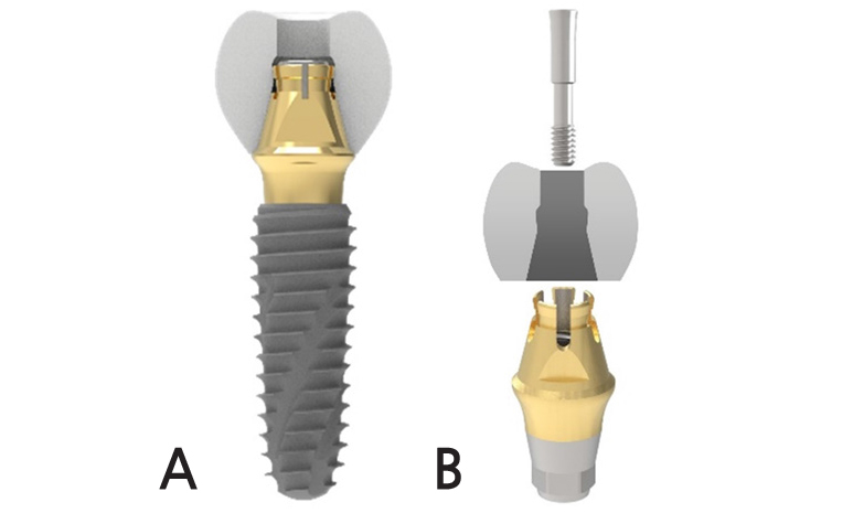
The Spread Fit Ti-Base System (SFIT; Cowellmedi, Busan, Korea) consists of a new structural screwand abutment that spreads the upper part of the abutment when screwing and is engaged to the groove on the inner surface of the prosthesis so that retention can be obtained without cement. Because of 11° taper of the Spread Fit abutment, axial divergences up to 22° between two implants can be compensated with these tapered abutment (Figs. 1 and 2).
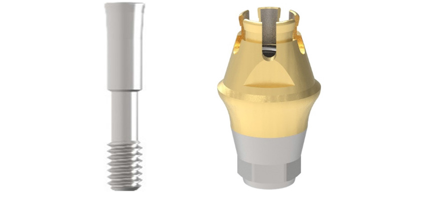
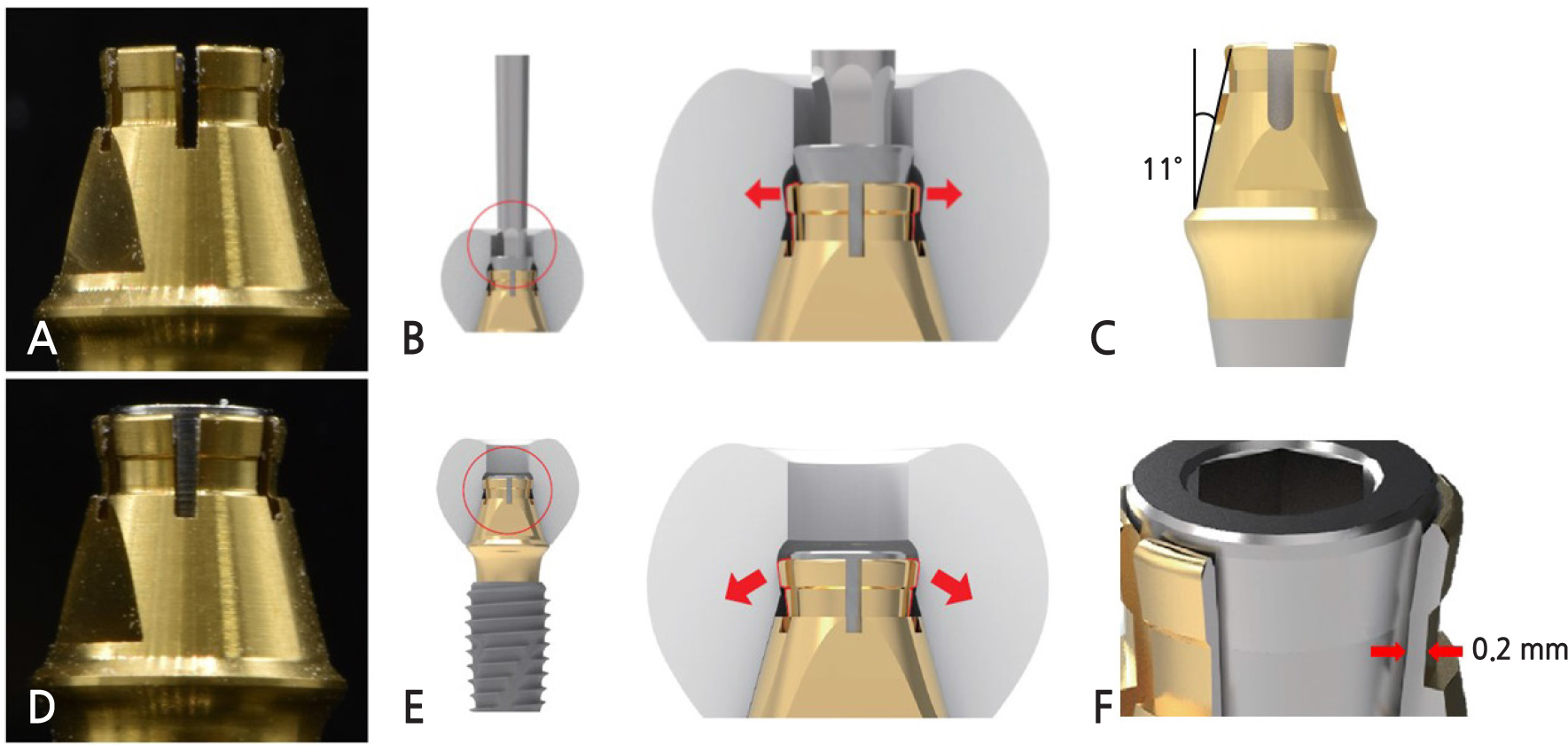
Fig. 2
(A), (B) SFIT Ti-Base system abutment and the prosthesis before screwing (C) 11° tapered SFIT Ti-Base system abutment (D), (E) After screwing, the upper part of the SFIT Ti-Base abutment is spread and engaged to the groove on the inner surface of the prosthesis(arrow). (F) The part where it spreads out from Spread Fit abutment has a thickness of 0.2 mm.
This case reports the functional and aesthetically satisfactory results obtained by treating a partially edentulous patient with an implant-fixed prosthesis using Spread Fit Ti-Base system.
Ⅱ. Case Report
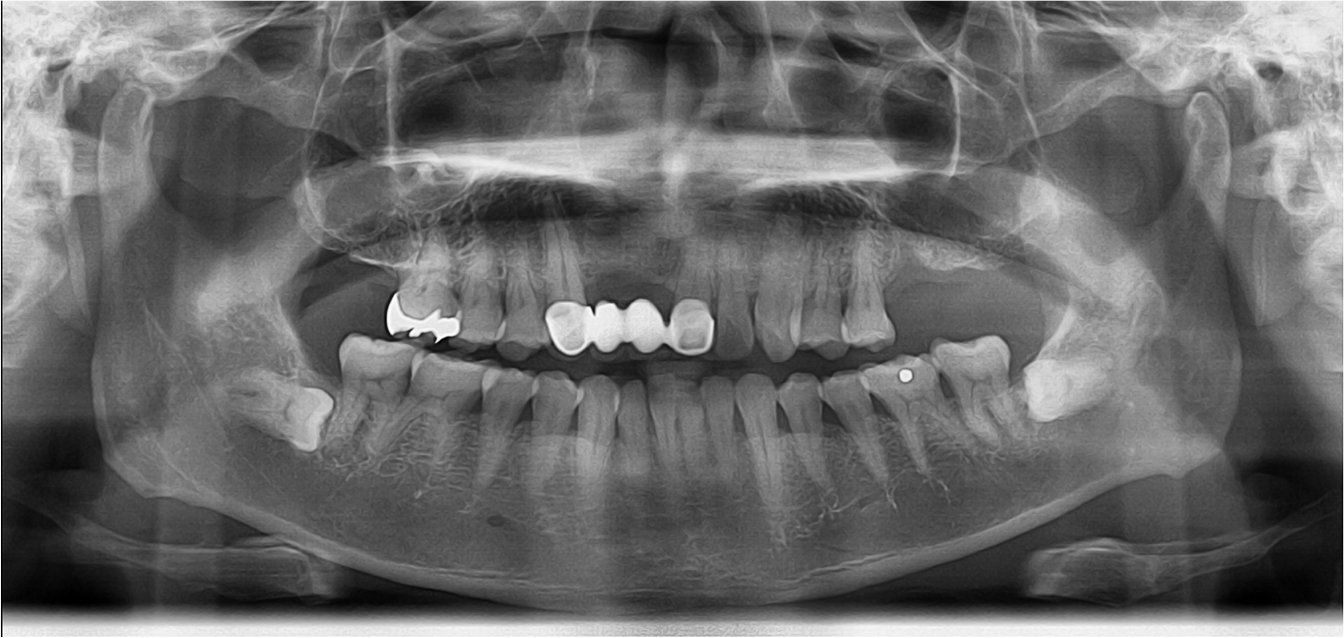
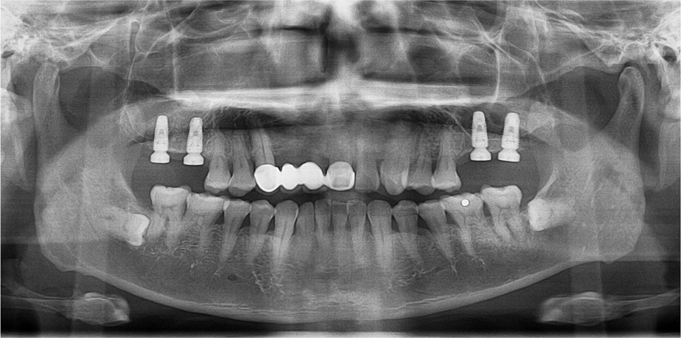
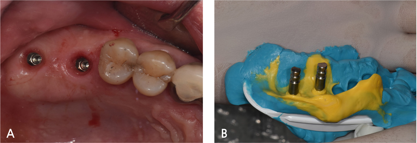
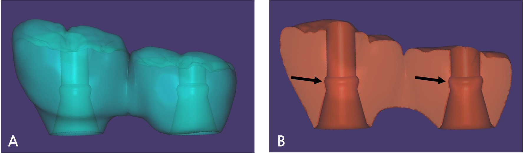
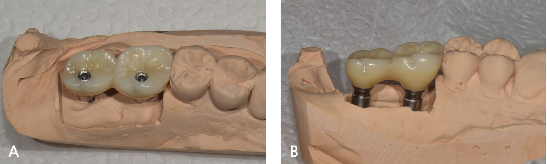
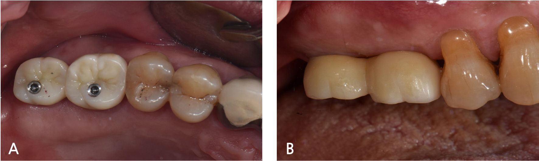
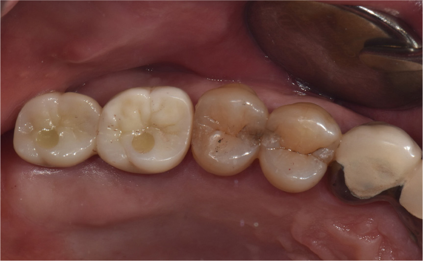
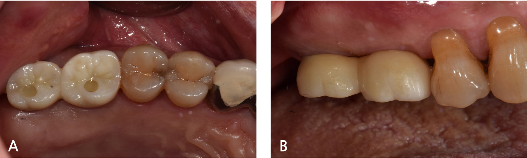
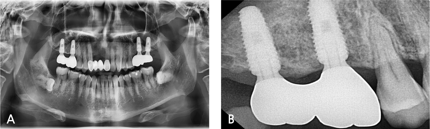
A 55-year-old male visited the dental clinic to restore his right maxillary posterior edentulous site with an implant-fixed prosthesis. His medical and dental histories were unremarkable. Considering the clinical and radiographic examination results, the right maxillary first molar was extracted as it was expected to have a poor prognosis (Fig. 3). Approximately six months after the right maxillary first molar extraction, 5.0×10.0 mm and 5.0×12.0 mm submerged implants (INNO; Cowellmedi) were placed on the edentulous sites of the right maxillary first and second molars, respectively. After confirming the good initial insertion torque of 30N·cm or greater in all implants, the healing abutment was connected (Fig. 4). Three months after the implant placement, stable osseointegration was verified with the implant stability quotient value. Bite impression coping (Cowellmedi) was connected to the right maxillary first and second molar implants, and the master model was fabricated after fixture level impression using silicone impression materials (PEAKOSIL; Neosil, Yangsan, Korea) and a plastic bite tray (Fig. 5). A Scanbody (Cowellmedi) was connected to the master model, and the model was scanned using a laboratory scanner (E3; 3Shape, Copenhagen, Denmark) to design the prosthesis with the CAD program. The inner surface of the prosthesis was designed according to the SFIT abutment library data so that the abutment and the groove on the inner surface of the prosthesis can be accurately engaged (Fig. 6). Using the CAD design, a monolithic zirconia fixed prosthesis was fabricated by 5-axis milling machine (Arum 5x-300; DoowonID, Daejeon, Korea)(Fig. 7). First, the SFIT abutment and prosthesis were tried in to evaluate its fit, aesthetics, and occlusion. Then the SFIT abutment and the prosthesis were engaged with the screw tightened to 30 N·cm (Fig. 8), and the occlusal screw holes were filled with composite resin (Filtek Z350 XT; 3M ESPE, MN, USA) (Figs. 9 and 10). After three months, there were no biological complications at follow-up, and the occlusion remained stable (Figs. 11 and 12).

Ⅲ. Discussion
In this case, a monolithic zirconia-fixed prosthesis was fabricated with Spread Fit Ti-Base system, a novel implant prosthesis system. In Spread Fit Ti-Base system, the upper part of the abutment was spread continuously when the screw was tightened to 30 N·cm (according to the manufacturer's recommendations), and the abutment engaged to the groove on the inner surface of the prosthesis. The groove depth of 0.5 mm is recommended to obtain retention.
In cement-retained prosthesis, the residual cement can cause peri-implantitis. Korsch et al. evaluated 126 implants and detected residual cement in 59.5%, and bleeding on probing was observed from 80% of those implants with residual cement. Suppuration was detected in 21.3%.10 Spread Fit Ti-Base system does not use cement so that these biological complications can be avoided. It can also be used in cases of insufficient intermaxillary space because Spread Fit Ti-Base system obtains retention with screw and not cement.6,11
Moreover, since the abutment and the prosthesis are separated when the screw is unscrewed, it is easier to repair and maintain than the screw-cement retained prosthesis in which the abutment and the prosthesis are cemented (Fig. 13).
However, because a screw engaged the abutment and the prosthesis, there is the disadvantage that an occlusal screw hole is necessary. It can only be used in an internal connection type implant, and it is difficult to manufacture a customized Spread Fit abutment. Internal connection type implant abutments have an axial displacement of about 30μm from the screw tightening and functional load, so there is less error to make the definitive prosthesis by taking an impression at the abutment level.12,13 On the contrary, Spread Fit Ti-Base system has a disadvantage in that it is difficult to manufacture a prosthesis by taking an impression at the abutment level. It is necessary to manufacture it by taking a fixture level impression, as an error may occur due to axial displacement.
The part where it spreads out from Spread Fit abutment has a thickness of 0.2 mm (Fig. 2). There is the risk of fracture upon repetitive application of the prosthesis and functional load; therefore, further study is required about the strength of this abutment. Additional study is also required whether micro-leakage occurs in an environment similar to that of the intraoral.
Ⅳ. Conclusion
Spread Fit Ti-Base system is convenient as it provides easy retrievability and can obtain the retention of the implant prosthesis without cement. This can prevent biological complications from residual cement, and its maintenance is fairly simple. Furthermore, it can be used in a narrow intermaxillary space, and it is easy to manufacture a prosthesis by CAD/CAM system. Spread Fit Ti-Base system, with these benefits, can be used to restore an implant-fixed prosthesis, although further studies are required to verify its clinical feasibility.
