

I. Introduction
Due to the high survival rate of implant-supported prostheses (ISPs) and continuous advancements in implant prosthodontics over time, ISPs have proved to be a reliable treatment option1,2. Conventional impressions using open or closed tray impression transfer copings have been widely used for the accurate transfer of implant position to a definitive cast3. Recently, intraoral digital impressions using scan bodies have gained popularity due to the high level of impression accuracy, clinical efficiency, and increased patients’ satisfaction4-6. However, repeated abutment dis/reconnection is still necessary during analog or digital impression procedures. Abrahamsson et al.7 described that repeated abutment change compromised the mucosal barrier and resulted in an apical positioning of the connective tissue. Peri-implant bone resorption was also observed to establish a proper biological width of the mucosal-implant barrier7-9. Therefore, minimizing the number of abutment removal is desirable to reduce the bone resorption and to achieve better esthetic results and patients’ convenience7-9.
A digitally coded healing abutment (BellaTek Encode Healing Abutment, Zimmer Biomet, Palm Beach Gardens, FL, USA) can be an alternative10-25. It is remained until placement of an ISP after placing on the implant at the time of implant surgery or uncovering10, 14-20. After a conventional impression is made, a dental cast is sent to the machining center (BellaTek Production Center, Zimmer Biomet)10-14, 18-20. A laser scanner recognizes the embedded codes on the BellaTek Encode Healing Abutment that convey information relative to the implant hex position, the platform diameter, the connection type, and the height/width of the abutment10-14, 19-21, 24, 25. With computer-aided design and computer-aided manufacturing (CAD/CAM) technology, a definitive dental implant abutment is virtually designed and milled10-14, 18-20. With a robotic analog implant placement technique (Robocast Technology, Zimmer Biomet), a hole is made in the cast and an implant analog is manually placed into a hole with cyanoacrylate adhesive (Two-part cyanoacrylate adhesive, Zimmer Biomet)14, 18-25. The CAD/CAM abutment and the modified cast (Robocast, Zimmer Biomet) are shipped to a laboratory14, 18-20, 25. Therefore, a dental technician fabricates only a definitive crown10-14, 18-20, 25.
Recently, the intraoral scanning technology has been applied to the BellaTek Encode System15-17, 20. After digitizing the BellaTek Encode Healing Abutment with an intraoral digital scanner (IOS), the scan data are electronically sent to the BellaTek Production Center and a patient-specific abutment is fabricated15-17, 20. Additionally, a stereolithography additive (SLA) cast is generated in 3M ESPE by using an abutment design file mailed from the BellaTek Production Center15-17, 20. The milled abutment and the printed cast are conveyed to a laboratory15-17, 20. Therefore, fabricating a Robocast or a SLA cast is required for subsequent fabrication of a definitive crown14-20, 25. Carpentieri and Lazzra19 expected that the next technical advancement would be a completely cast-free, digital workflow for implant prosthodontics.
The purpose of the present article is to introduce a fully digital workflow with an advanced coded healing abutment. By using this streamlined process, an ISP can be rapidly fabricated without repeated abutment dis/reconnection, physical cast, and human error.
II. Case Report
A 66-year-old male presented with pain in the maxillary right second molar. Based on the results of clinical and radiographic examinations, the diagnosis was a tooth fracture indicated for extraction. The patient had no systemic diseases to undergo the surgical procedure. For the replacement of the tooth, advantages and disadvantages of a single dental implant were explained. The patient hoped to receive implant treatment. After an atraumatic extraction, a 4.5×10 mm bone level implant (Implantium, Dentium, Suwon, Korea) was placed in the first-stage dental implant surgery. A coded healing abutment (H-Scan Body, Dio Implant Inc, Busan, Korea) was hand tightened19.
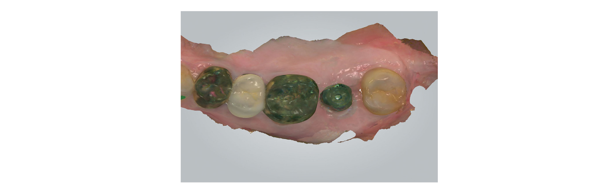
After 5 months, the complete placement of the H-Scan Body on the implant was reverified with an abutment driver dental implant (1.2 Hex Screw Driver, Dio Implant Inc) and a radiograph (Figs. 1 and 2)19. The H-Scan Body was circumferentially extended by 3 mm above the gingiva19. Plaque accumulation on the occlusal surface of the H-Scan Body was removed for the accurate superimposition in a CAD process. The maxillary right teeth and the H-Scan Body were scanned with an IOS (TRIOS Color Pod, 3Shape Inc, Copenhagen, Denmark) (Fig. 3)26-29. The antagonist teeth and maxillomandibular relationship was captured. The scan data, implant information, and H-Scan Body information were transmitted to a laboratory.


By using a CAD program (Dental System, 3Shape Inc), the scan data were opened. The scanned image of the H-Scan Body was aligned with the stored image of the SB by using a 3-point matching technique (Figs. 4 and 5)6. A retrievable cemented ISP was planned for passivity and easy removal of excess cement30-33. A custom abutment and a crown with a screw-access opening were designed (Fig. 6)30-33. The finished design was transferred to 5-axis milling machines (Arum 5X-200, DoowonID Co, Daejeon, Korea). A titanium blank and a cobalt-chromium alloy block were milled simultaneously.

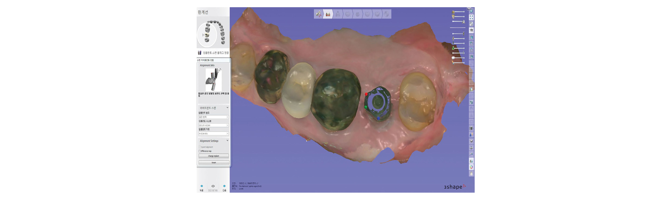
Fig. 4
Software view of the stored image of the coded healing abutment in the computer-aided design program. A 3-point matching technique is applied for the superimposition of the stored image and the scan image.
Ju-Hyoung Lee: A Completely Cast-Free, Digital Workflow for Fabricating an Implant-Supported Prosthesis with a New Coded Healing Abutment. Implantology 2019

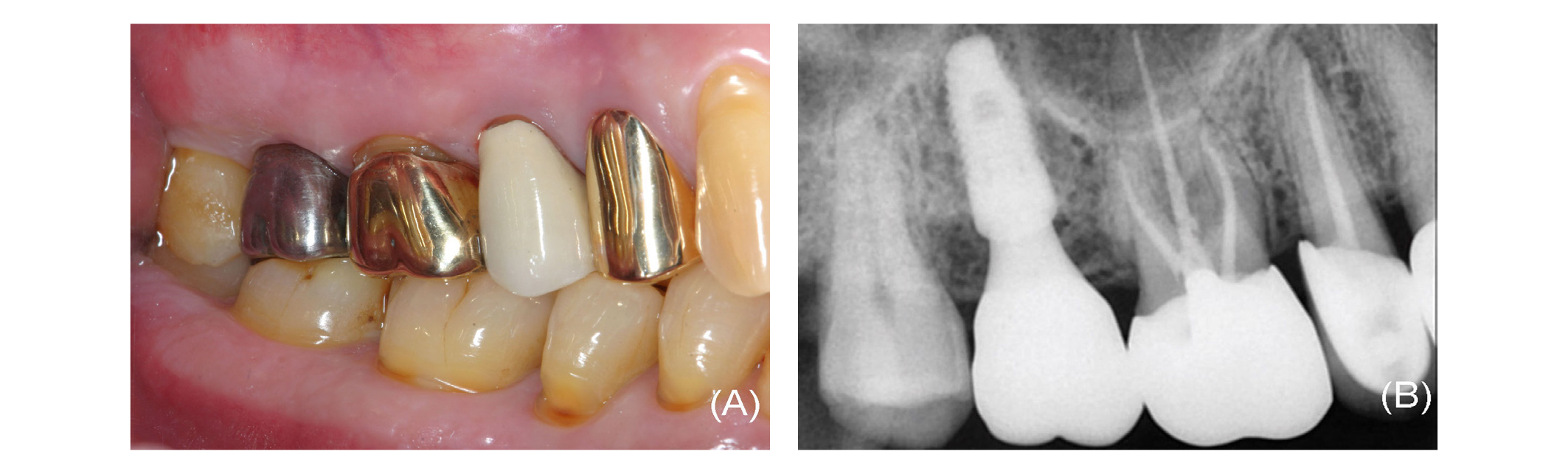
The H-Scan Body was removed and topical anesthetic (Beracaine Spray, Firson, Cheonan, Korea) was applied on the peri-implant soft tissue34. The custom abutment was secured to the implant up to three-fourths the recommended manufacturer instruction torque value35, 36. Proximal contacts and occlusal contacts of the crown were evaluated and adjusted with an articulating film (AccuFilm II, Parkell Inc, Edgewood, NY, USA). The internal surface of the crown was abraded with 50 µm alumina oxide particles (Cobra, Renfert GmbH, Hilzingen, Germany) at 3 bar pressure for 10 seconds, at the distance of 10 mm from the nozzle of the sandblaster (Duostar, Bego, Bremen, Germany)37. After cleaning the crown, a primer (Monobond Plus, Ivoclar Vivadent Inc, Schaan, Liechtenstein) was applied to the internal surface. The crown was luted with resin cement (Multilink Automix, Ivoclar Vivadent Inc). After the polymerization, the ISP was retrieved extraorally and all excess cement was eliminated. The ISP was torqued on the implant according to the manufacture’s protocol and the screw access channel was filled with silicone material38, 39. The screw-access opening was restored with composite resin (UniFil LoFlo Plus, GC Corp, Tokyo, Japan) (Fig. 7). At-home maintenance regime and recall appointments were provided40, 41. Stable peri-implant tissue was observed at 1 year follow-up (Fig. 8).

Ⅲ. Discussion
The BellaTek Encode system has been successfully applied in patients10-20. This innovative system minimizes peri-implant tissue irritation and provides a more efficient restorative process10-20. As the healing abutment-level impression is only necessary, this system is useful for a deeply placed implant14-20. It also saves a laboratory technician’s time by eliminating labor-intensive procedures such as waxing and casting10-20, 25. However, this system has several limitations. First, use of this system is applicable only to a specific implant (Biomet 3i Dental Implants, Zimmer Biomet)12, 14. A second disadvantage is that total time to return an ISP from a laboratory is similar to a conventional protocol with a prefabricated abutment, due to the outsourcing production and the associated delivery time25. A third disadvantage is inaccurate positioning of an implant analog into a hole in a stone cast, due to the robotic accuracy (100 um)22, a slightly oversized hole (0.4 mm)24, and polymerization shrinkage of the cyanoacrylate adhesive (17.8%)23, 41. Dimensional changes of impression materials43 and dental stone44 also increase the error. In addition, implant divergence negatively affects the Robocast accuracy22, 24. Even though an IOS and a SLA cast are used to reduce the cumulative error15-17, marginal discrepancy may occur due to the lower accuracy and reproducibility of a SLA die45, 46. The outsourcing production of the CAD/CAM abutment in the BellaTek Production Center may cause the second and third drawbacks. Therefore, merging the BellaTek Encode and intraoral scanning technologies with the scan body technology is necessary to eliminate possible errors and to respond to the need for the outsourcing production.
Recently, the H-Scan Body is developed to overcome the aforementioned limitations. As this coded healing abutment is basically based on the BellaTek Encode Healing Abutment, it also reduces repeated abutment change, patients’ discomfort, and chair time. The H-Scan Body can be applied various implants, if the CAD program has a library of installed implant. Another advantage is the accelerated fabrication of implant prostheses with the laboratory friendly CAD/CAM program.
However, this technique also has several limitations. One disadvantage is the initial purchasing costs for the IOS, the H-Scan Body, and its module. Another disadvantage is learning curve for intraoral scanning procedures, especially, in the posterior area, due to the limited space for the IOS head16, 27, 28. A third disadvantage is difficulty in establishing an ideal emergence profile due to the polygonal shape of the H-Scan Body30, even if an algorithm formula is helpful to predict displacement of the soft tissue and the future position of the gingival margin after ISP placement47. Transient blanching and pain on insertion may occur25. Development of the wide H-Scan Body is necessary for easy seating of the ISP at the molar site. Even though the CAD/CAM abutments have exhibited the proper survival rate,48 postoperative care should be necessary to prevent unexpected complications40, 41. In addition, the influence of implant divergence on the three-dimensional accuracy of the impression technique using the H-Scan Body and compatibility of coded healing abutments should be investigated.
