

I. Introduction
Fabricating a well-fitted single crown restoration related to an existing denture is a challenging procedure; in many cases, the denture may not fit appropriately on the retro-fitted crown. A few ideas have been suggested to resolve this limitation to the date. In the past, direct-indirect approaches were suggested to fit the crown with regard to the existing denture1-5.
With the advancement of digital technologies, several authors reported methods to fabricate retro-fitted crowns based on the computer-aided design / computer-aided manufacturing (CAD/CAM) techniques6-9. A variety of CAD technologies have been developed in dental fields, impacting on all aspects of dentistry; however, in reality, their functions are not fully utilized10,11. The present case described herein successfully placed a retro-fitted crown restoration under an existing denture by employing the characteristics of digital technology that enabled deletion of superimposed area in 3-dimensional (3D) aspect. The original intentions of the menu in the CAD software were modified to achieve this.
II. Case report
A 73-year-old male patient presented to the Department of Prosthodontics at Yonsei University Dental Hospital for fabrication of a single crown restoration under an existing denture. Digital intraoral scans were obtained in occlusion without wearing the existing denture by using an intraoral scanner (Trios 3; 3Shape) (Fig. 1). Then, the entire surfaces of the existing denture were scanned with a tabletop scanner (T500; Medit Co) (Fig. 2). The maxillary digital intraoral scan and the scanned old denture were superimposed by best-fit matching algorithm after selecting three pairs of points for matching in CAD software (Exocad DentalCAD; Exocad GmbH) (Fig. 3). The superimposed maxillary data were saved in the standard tessellation file (STL) format while maintaining their relationship with the mandibular data. Proper fit of the denture on the maxillary arch was evaluated in the software by referring to the sectional view.
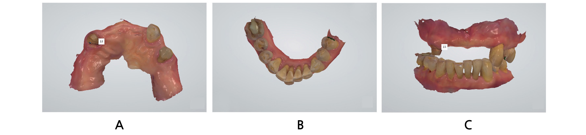

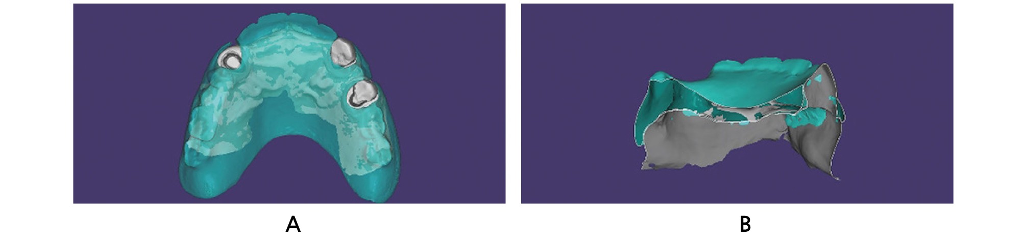
Fig. 3.
Superimposition of the maxillary digital intraoral scan and the scanned old denture data sets. A: Superimposition of the maxillary digital intraoral scan and the scanned old denture data sets by best-fit matching algorithm. B: Sectional view to confirm the fit of the denture on the maxillary arch.
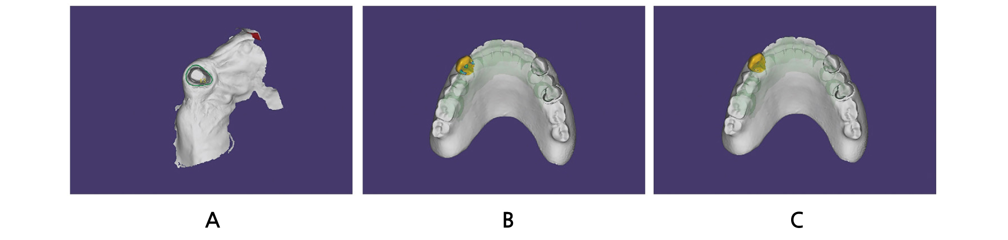
An “Anatomic crown” module was selected for the tooth to be restored, “Adjacent tooth” modules were chosen for the adjacent teeth, and “Antagonist” modules were selected for the antagonists in a new project file. The margins were defined and the shape, contour, and occlusion of the virtual crown were adjusted (Fig. 4). The crown was designed in a slightly larger than the ideal size.
An “Approx.” option in the “Select type of adaptation:” menu was chosen followed by the “Cut intersections” option, in order to adapt the virtual crown to the existing denture. The denture is regarded as an adjacent tooth and the software automatically cut the portion of the virtual tooth that extended over the denture (Fig. 5). A minor adjustment was performed to the virtual crown, and the crown was fabricated with a polymethylmethacrylate (PMMA) disc and a milling machine (Fig. 6).
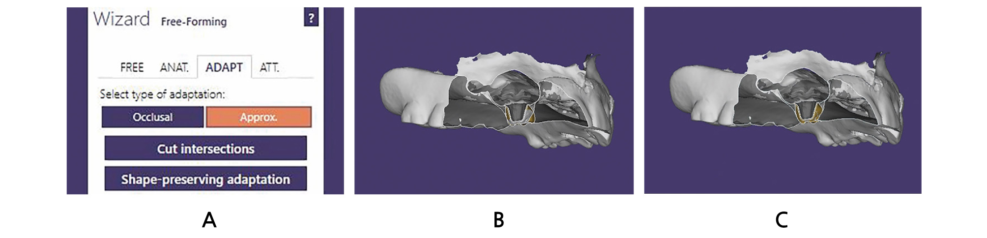
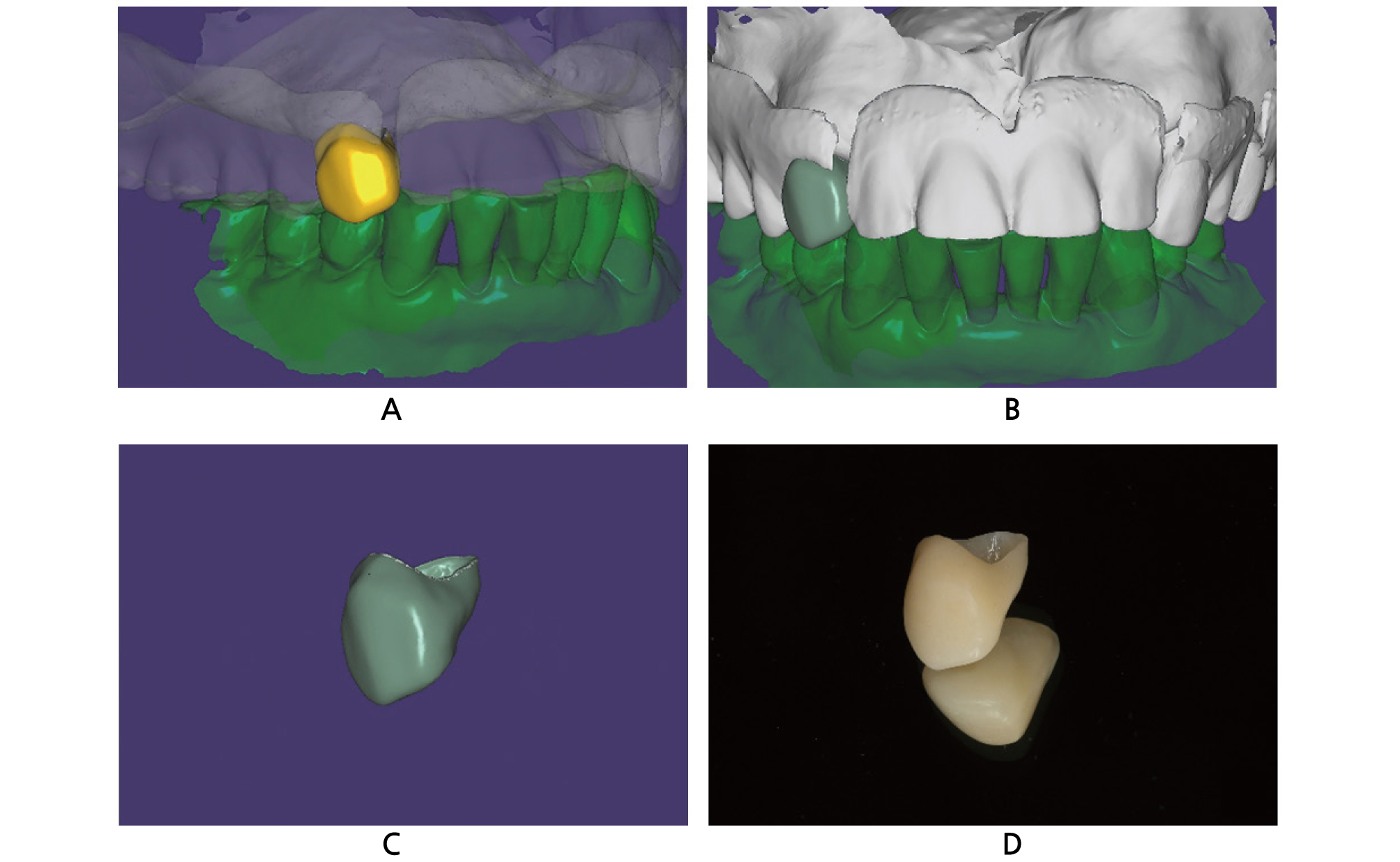
Fig. 5.
Adaptation procedures of the virtual crown. A: Clicking of “Approx.” option in “Select type of adaptation:” menu followed by “Cut intersections” option. B: Before adaptation of the virtual crown to the old denture in sectional view. Yellow-colored area indicates portion of the virtual crown. C: After adaptation of the virtual crown to the old denture in sectional view. Yellow-colored area indicates portion of the virtual crown.
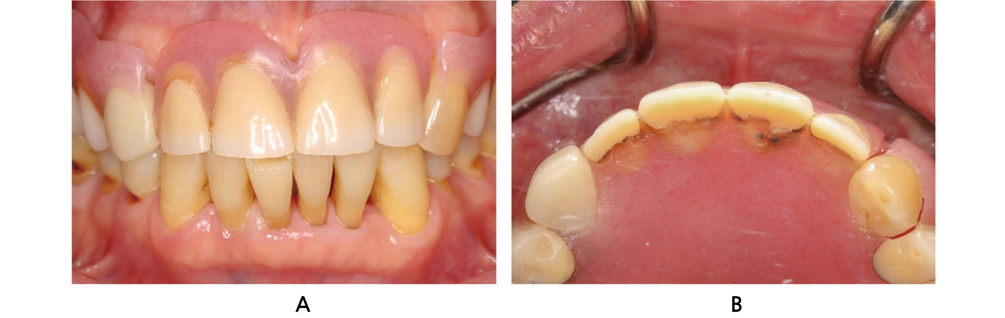
The fabricated PMMA crown and the old denture were placed in the patient’s mouth, and the relationship of the crown with the old denture was evaluated to examine if the crown is too tight or too loose with regard to the denture. After checking the esthetics and occlusion, the crown was cemented with a resin-modified glass ionomer cement (Rely X Luting 2 Cement; 3M ESPE) (Fig. 7). The patient expressed satisfaction with the outcomes of the retro-fitted crown.
III. Discussion
The retro-fitted crown restoration was successfully placed in the patient’s mouth by automatically cutting the portion of the virtual crown that extended over the existing denture area in 3D aspects. The procedure was possible because the old denture was set to be regarded as an adjacent tooth. The virtual crown was adapted to the “adjacent area”, which refers to the old denture, on selecting the “Cut intersections” option.
This approach could broaden its application range to a variety of materials because the values related to the amount of adaptation can be adjusted. Specifically, fabrication of retro-fitted surveyed crowns that are placed on the metal frameworks of removable dental prostheses would be valuable in the future, although the process involves difficulties of scanning metal structures such as clasps, occlusal rests, and minor connectors. It is the clinicians’ role to investigate the most appropriate values according to the materials or the computer-aided manufacturing machines they possess by trial and error to apply the present workflow.
The present case significantly reduced the chairtime to adjust the crown to fit appropriately with the existing denture. It may further reduce a clinical situation that might require remaking the denture. Accordingly, patients can use their accustomed old denture for an extended period. Further in vitro studies assessing the accuracy of this retro-fitted crown with regard to the existing denture may also be worth investigating.
IV. Conclusion
A single crown restoration was easily placed under an existing denture by applying digital technology. This retro-fitted crown restoration was fabricated based on the idea to set the old denture as an adjacent tooth; the portion of the virtual crown that extended over the denture areas was cut by applying the “Cut intersections” option. The patient was satisfied to use his accustomed old denture for an extended period. Further studies assessing the applicability to other prosthodontic materials would be of a great value.
